Ratio, shaft angle and mounting geometry answer different questions about the same spiral bevel gear pair. Ratio describes the relationship between the tooth counts. Shaft angle describes how the two axes intersect. Mounting geometry describes where the two finished components are positioned in the housing. Treating any one of these as a complete definition can lead to a pair that looks plausible but does not fit the intended assembly.
Put ratio and axis relationship on the same assembly definition
A ratio can be written as tooth counts or as a numerical relationship, but the drawing should identify which count belongs to the gear and which belongs to the pinion. The shaft angle should be tied to the assembly axes, not inferred from the outside shape of the gear blank.
For replacements, measure the housing or shaft arrangement that establishes those axes. A loose bearing or damaged support can make an “as found” angle misleading.
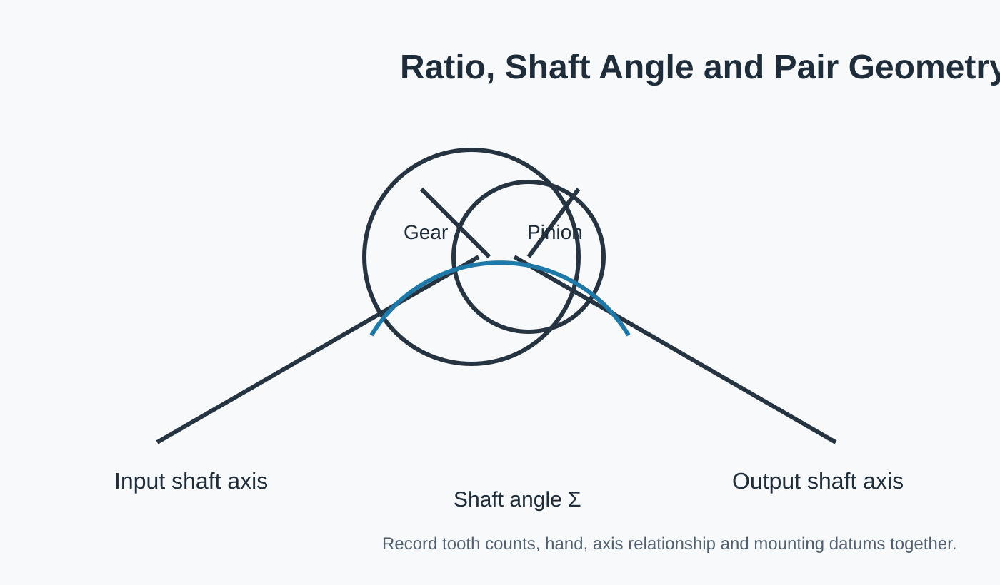
Four geometry groups to keep together
| Geometry group | Typical content | なぜそれが重要なのか |
|---|---|---|
| Ratio | Gear and pinion tooth counts | Defines the speed/torque relationship of the pair. |
| Axis relationship | Shaft angle and orientation | Defines how the two shafts intersect. |
| Tooth orientation | Right/left hand and spiral direction | Defines the mating tooth orientation. |
| 取り付け | Mounting distance, datums and backlash | Defines where the gears sit in the actual housing. |
Mounting geometry connects the drawing to the machine
The same tooth geometry can behave differently if the pair is installed away from the intended position. Bearing seats, shoulders and shims can all influence the final location. If backlash or contact is an acceptance item, the drawing and assembly instruction should make the reference condition clear.
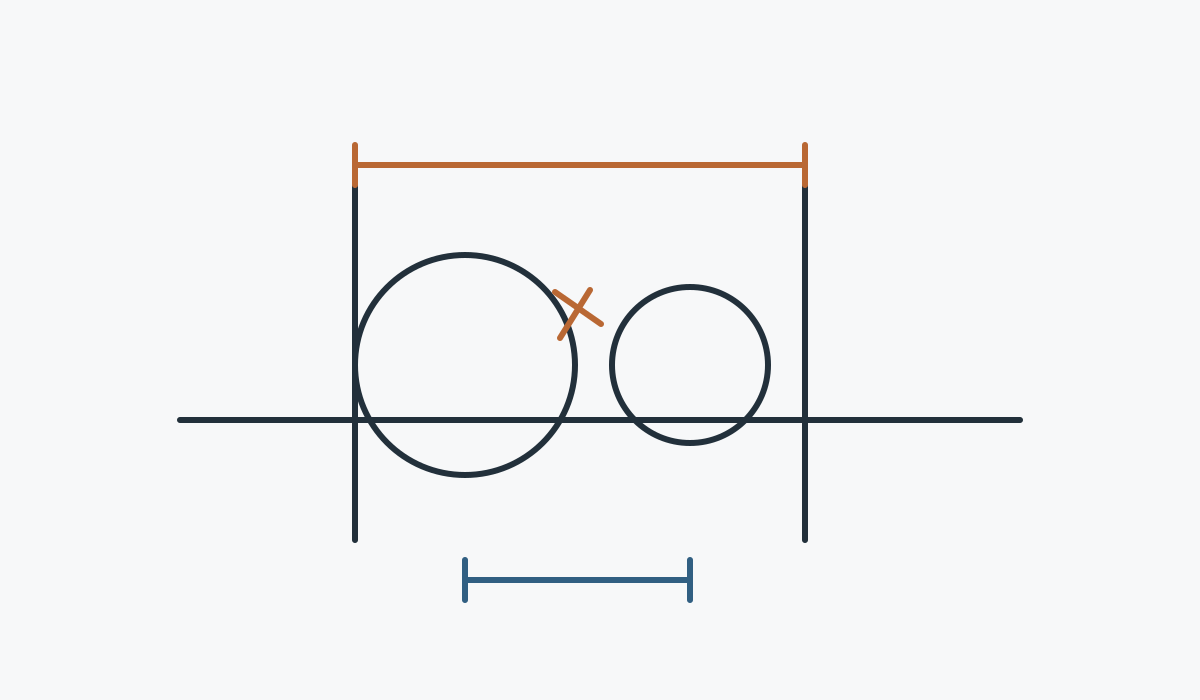
What to send in a replacement RFQ
Send both members if possible, the tooth counts, the orientation of each shaft, the housing/bearing references, measured backlash if reliable, and any legacy drawing. If the original pair is badly worn, document the machine before dismantling so the replacement review can distinguish the intended geometry from the damaged condition.
Common drawing omissions
Drawings sometimes show tooth count and outside dimensions but omit the axis relationship or the mounting reference. Others list a ratio without identifying which member is the pinion. These omissions are manageable during design, but they become expensive when a supplier must reconstruct intent from separate emails.
Use an assembly view or clear notes to connect the pair. If the shaft angle is not the common arrangement for your machine, make it impossible to overlook. If the pair is a replacement, show the existing housing axes and the datum surfaces used for measurement.
Questions buyers often ask
Does 1:1 ratio automatically mean a miter gear set?
Equal tooth count is consistent with a miter arrangement, but the hand, shaft angle and mounting geometry still need to be defined.
Can shaft angle be measured from the gear faces?
Use the actual shaft or housing axes when possible. Gear faces may not be the controlled assembly references.
Why include mounting data on a tooth-geometry drawing?
Because the pair must be positioned correctly in the machine. Mounting information links the manufactured geometry to the working assembly.
ギアペア、図面、および仕様を1つの見積依頼書にまとめて送付してください。
接合関係と組立基準が明確に定義されていればいるほど、構成の確認は迅速に行える。
注文と配送に関するご案内
最小発注数量(MOQ)は、製品の種類、製造方法、および注文総額によって柔軟に対応可能です。適切な新規プロジェクトでは、サンプル価格で1~5個のサンプルを注文できます。注文総額が約1,500米ドルに達した場合、複数のモデルを組み合わせることができます。1~2個の注文も検討可能ですが、通常は単価が高くなります。
標準部品の一般的な納期は10~25営業日、特注部品は20~45営業日、プロジェクト型機器または組立品は45~120営業日です。EXW、FOB、CIF、DAPは一般的に対応可能ですが、FCA、CFR、CPT、CIP、DDPについてはご相談ください。

























