Le rapport de denture, l'angle d'arbre et la géométrie de montage répondent à différentes questions concernant une même paire d'engrenages coniques à denture hélicoïdale. Le rapport de denture décrit le rapport entre le nombre de dents. L'angle d'arbre décrit l'intersection des deux axes. La géométrie de montage décrit la position des deux composants finis dans le carter. Se baser uniquement sur l'un de ces éléments peut aboutir à une paire d'engrenages qui semble plausible, mais qui ne s'intègre pas à l'assemblage prévu.
Intégrez le rapport et la relation d'axe dans la même définition d'assemblage.
Un rapport peut être exprimé en nombre de dents ou sous forme numérique, mais le dessin doit clairement indiquer quel nombre de dents correspond à la roue dentée et quel nombre correspond au pignon. L'angle de l'arbre doit être déterminé par rapport aux axes d'assemblage et non déduit de la forme extérieure de l'ébauche de la roue dentée.
Pour les pièces de rechange, mesurez le logement ou l'arbre qui définit ces axes. Un roulement desserré ou un support endommagé peut fausser l'angle mesuré.
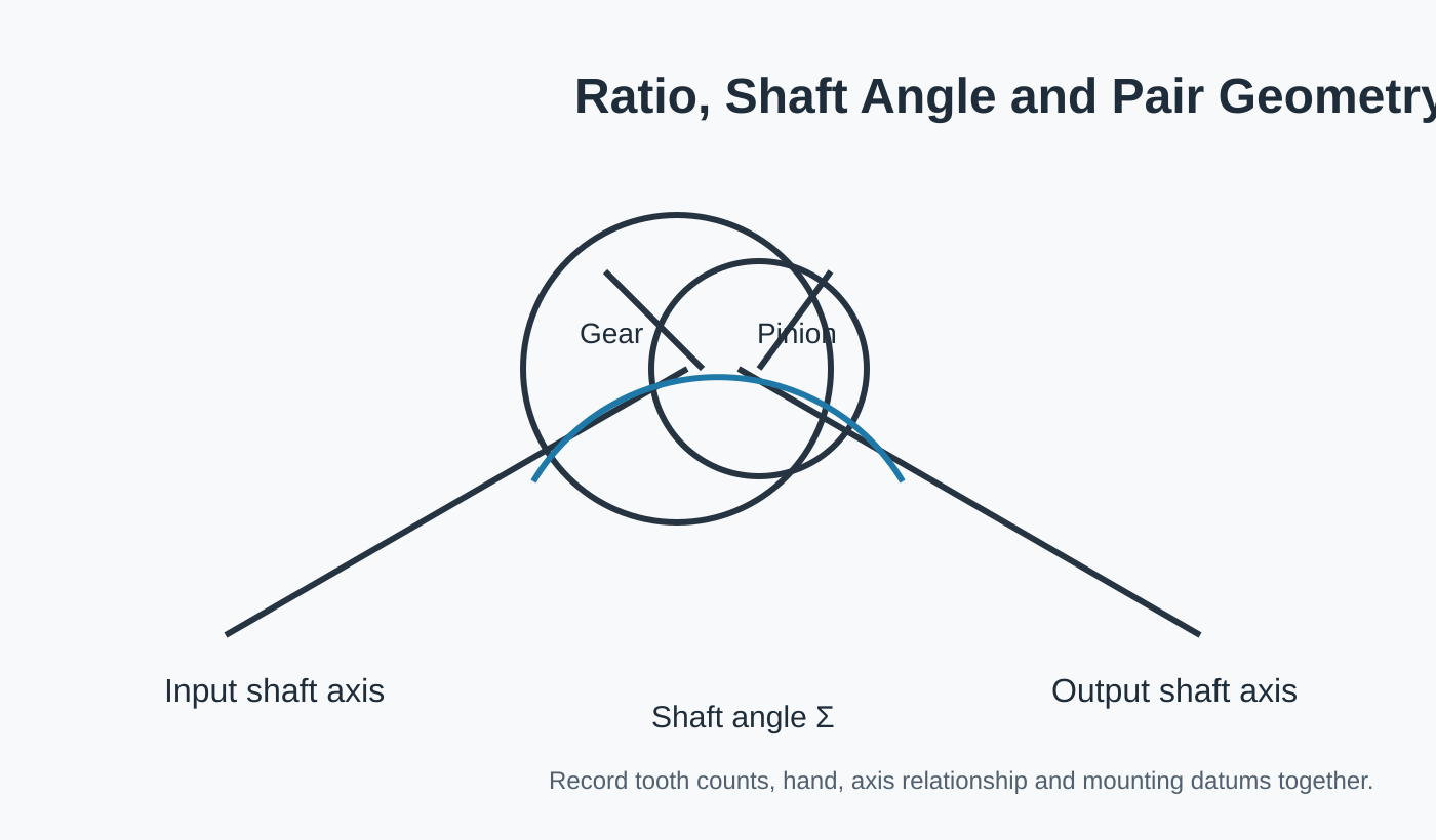
Quatre groupes de géométrie à garder ensemble
| Groupe de géométrie | Contenu typique | Pourquoi c'est important |
|---|---|---|
| Rapport | Nombre de dents des engrenages et des pignons | Définit la relation vitesse/couple de la paire. |
| Relation d'axe | Angle et orientation de l'arbre | Définit comment les deux arbres se croisent. |
| Orientation des dents | Main droite/gauche et direction en spirale | Définit l'orientation de la dent d'accouplement. |
| Montage | Distance de montage, références et jeu | Définit l'emplacement des engrenages dans le boîtier. |
La géométrie de montage relie le dessin à la machine
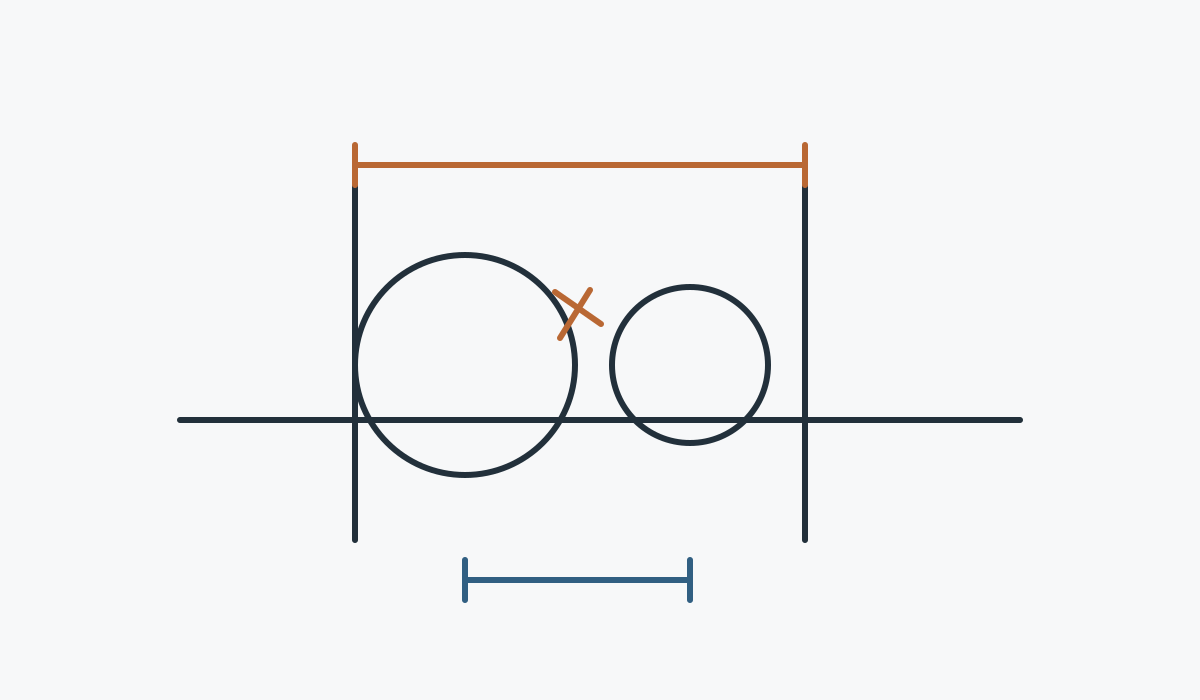
Une même géométrie de dent peut se comporter différemment si la paire est installée hors de sa position prévue. Les sièges de roulement, les épaulements et les cales peuvent tous influencer le positionnement final. Si le jeu ou le contact est un critère d'acceptation, le dessin et la notice de montage doivent clairement indiquer la condition de référence.
Que faut-il inclure dans une nouvelle demande de devis ?
Si possible, veuillez envoyer les deux éléments, le nombre de dents, l'orientation de chaque arbre, les références du logement/palier, le jeu mesuré (si la mesure est fiable) et tout schéma d'origine. Si la paire d'origine est fortement usée, documentez la machine avant démontage afin que l'examen du remplacement puisse distinguer la géométrie prévue de l'état endommagé.
omissions courantes dans les dessins
Les schémas indiquent parfois le nombre de dents et les dimensions extérieures, mais omettent le rapport d'axe ou la référence de montage. D'autres mentionnent un rapport sans préciser quel élément est le pignon. Ces omissions sont gérables lors de la conception, mais deviennent coûteuses lorsqu'un fournisseur doit reconstituer le descriptif à partir de courriels disparates.
Utilisez un schéma d'assemblage ou des notes claires pour relier les deux pièces. Si l'angle de l'arbre diffère de la configuration standard de votre machine, assurez-vous qu'il soit bien visible. S'il s'agit d'une pièce de rechange, indiquez les axes du carter existant et les surfaces de référence utilisées pour les mesures.
Questions fréquemment posées par les acheteurs
Un rapport de 1:1 signifie-t-il automatiquement un jeu d'engrenages à onglet ?
Un nombre égal de dents est cohérent avec une disposition en biseau, mais le sens d'attaque, l'angle de l'arbre et la géométrie de montage restent à définir.
Peut-on mesurer l'angle de l'arbre à partir des faces des engrenages ?
Utilisez les axes réels de l'arbre ou du carter lorsque cela est possible. Les faces des engrenages peuvent ne pas constituer les références de l'assemblage contrôlé.
Pourquoi inclure des données de montage sur un schéma de géométrie dentaire ?
Car les deux pièces doivent être correctement positionnées dans la machine. Les informations de montage permettent de relier la géométrie de fabrication à l'ensemble fonctionnel.
Veuillez inclure la paire d'engrenages, le schéma et le descriptif du service dans une seule demande de devis.
Plus les relations d'accouplement et les données d'assemblage sont définies clairement, plus la configuration peut être examinée rapidement.
Conseils pour les commandes et la livraison
La quantité minimale de commande (MOQ) est flexible et dépend du type de produit, du procédé de fabrication et du montant total de la commande. Pour les nouveaux projets, il est possible de commander de 1 à 5 échantillons à un tarif préférentiel. Différents modèles peuvent être combinés lorsque le montant total de la commande atteint environ 1 500 USD. Les commandes de 1 à 2 pièces peuvent être étudiées, bien que le coût unitaire soit généralement plus élevé.
Les délais de planification habituels sont de 10 à 25 jours ouvrables pour les pièces standard, de 20 à 45 jours ouvrables pour les composants sur mesure et de 45 à 120 jours ouvrables pour les équipements ou assemblages spécifiques à un projet. Les incoterms EXW, FOB, CIF et DAP sont couramment pris en charge ; les incoterms FCA, CFR, CPT, CIP et DDP peuvent être envisagés pour l’expédition.

























