La relación de transmisión, el ángulo del eje y la geometría de montaje responden a diferentes preguntas sobre el mismo par de engranajes cónicos espirales. La relación de transmisión describe la relación entre el número de dientes. El ángulo del eje describe cómo se cruzan los dos ejes. La geometría de montaje describe la posición de los dos componentes terminados en la carcasa. Considerar cualquiera de estos parámetros como una definición completa puede dar lugar a un par que parezca plausible, pero que no se ajuste al ensamblaje previsto.
Coloca la relación de proporción y de ejes en la misma definición de ensamblaje.
La relación puede expresarse como número de dientes o como una relación numérica, pero el dibujo debe indicar qué número corresponde al engranaje y cuál al piñón. El ángulo del eje debe estar vinculado a los ejes de montaje, no inferirse de la forma externa de la pieza en bruto del engranaje.
Para los reemplazos, mida la carcasa o el conjunto del eje que define dichos ejes. Un cojinete suelto o un soporte dañado pueden hacer que el ángulo inicial sea engañoso.
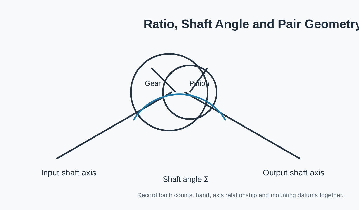
Cuatro grupos de geometría para mantener juntos
| Grupo de geometría | Contenido típico | Por qué es importante |
|---|---|---|
| Relación | Número de dientes de engranajes y piñones | Define la relación velocidad/par del par. |
| Relación de ejes | Ángulo y orientación del eje | Define cómo se cruzan los dos ejes. |
| Orientación del diente | Mano derecha/izquierda y dirección espiral | Define la orientación del diente de acoplamiento. |
| Montaje | Distancia de montaje, puntos de referencia y holgura | Define la posición de los engranajes dentro de la carcasa. |
La geometría de montaje conecta el dibujo con la máquina.
La misma geometría dentada puede comportarse de manera diferente si el par se instala fuera de la posición prevista. Los asientos, los hombros y las arandelas de ajuste de los cojinetes pueden influir en la ubicación final. Si el juego o el contacto son un elemento aceptable, el plano y las instrucciones de montaje deben especificar claramente la condición de referencia.
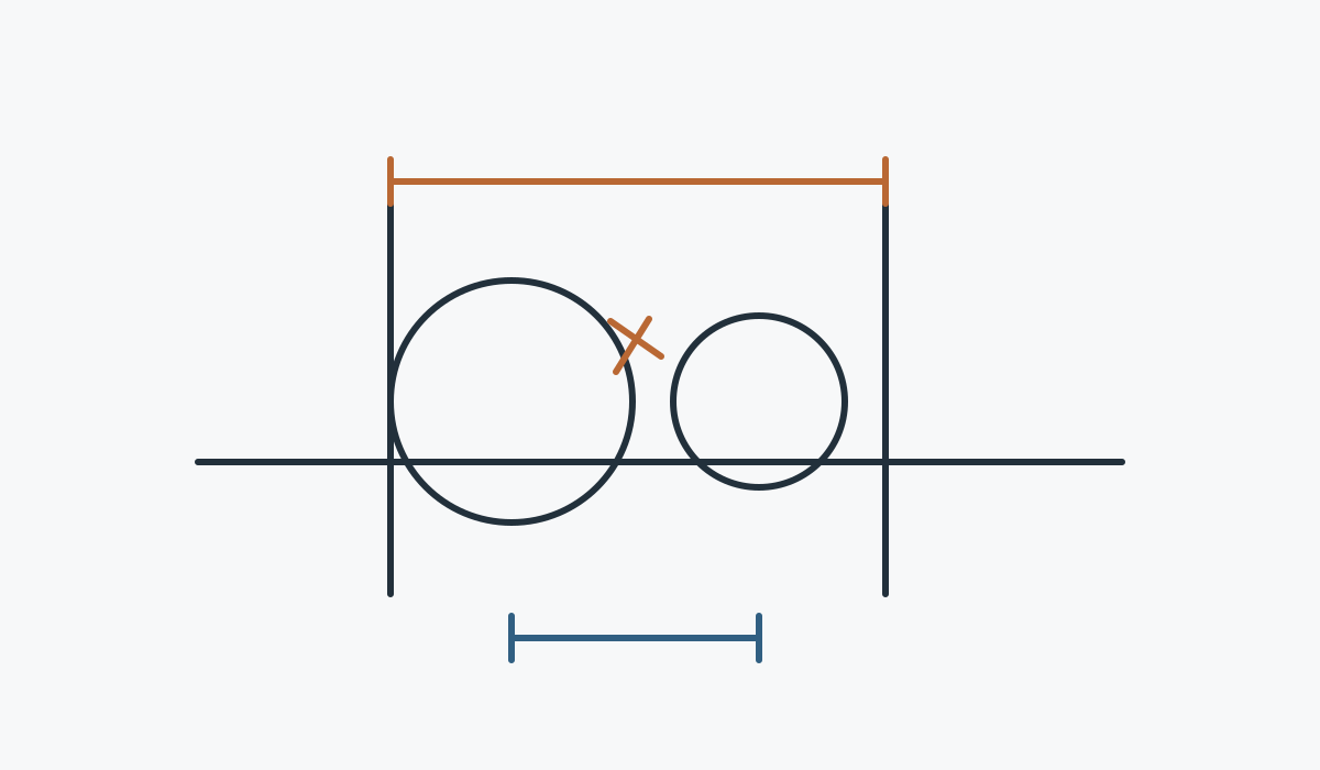
Qué enviar en una solicitud de cotización de reemplazo
Si es posible, envíe ambos elementos, el número de dientes, la orientación de cada eje, las referencias de la carcasa/cojinete, la holgura medida (si es fiable) y cualquier plano anterior. Si el par original está muy desgastado, documente la máquina antes de desmontarla para que la revisión de la pieza de repuesto permita distinguir la geometría prevista de la condición dañada.
Omisiones comunes en los dibujos
En ocasiones, los planos muestran el número de dientes y las dimensiones exteriores, pero omiten la relación de ejes o la referencia de montaje. Otros indican una relación sin especificar qué componente es el piñón. Estas omisiones son manejables durante la fase de diseño, pero resultan costosas cuando un proveedor debe reconstruir la intención a partir de correos electrónicos dispersos.
Utilice una vista de ensamblaje o notas claras para conectar las piezas. Si el ángulo del eje no es la configuración habitual de su máquina, asegúrese de que sea imposible pasarlo por alto. Si se trata de un reemplazo, muestre los ejes de la carcasa existente y las superficies de referencia utilizadas para la medición.
Preguntas que suelen hacer los compradores
¿Una relación 1:1 implica automáticamente un juego de engranajes para ingletes?
Un número igual de dientes es coherente con una disposición a inglete, pero aún es necesario definir la mano, el ángulo del eje y la geometría de montaje.
¿Se puede medir el ángulo del eje a partir de las caras de los engranajes?
Utilice los ejes reales del eje o de la carcasa siempre que sea posible. Es posible que las caras de los engranajes no sean las referencias de ensamblaje controladas.
¿Por qué incluir datos de montaje en un dibujo de la geometría del diente?
Porque el par debe colocarse correctamente en la máquina. La información de montaje vincula la geometría fabricada con el conjunto de trabajo.
Envíe el par de engranajes, el plano y la capacidad de carga en una sola solicitud de cotización.
Cuanto más claramente se definan la relación de acoplamiento y los datos de ensamblaje, más rápido se podrá revisar la configuración.
Guía para realizar pedidos y entregas
La cantidad mínima de pedido (MOQ) es flexible según el tipo de producto, el proceso de fabricación y el valor total del pedido. Los proyectos nuevos que cumplan con los requisitos pueden solicitar de 1 a 5 muestras a precio de muestra. Se pueden combinar diferentes modelos cuando el total del pedido alcance aproximadamente los 1500 USD. Se pueden revisar los pedidos de 1 a 2 unidades, aunque el costo unitario suele ser mayor.
Los plazos de planificación habituales son de 10 a 25 días hábiles para piezas estándar, de 20 a 45 días hábiles para componentes personalizados y de 45 a 120 días hábiles para equipos o conjuntos de tipo proyecto. Se suelen aceptar los términos EXW, FOB, CIF y DAP; para el envío, se pueden considerar FCA, CFR, CPT, CIP y DDP.

























