Il rapporto di trasmissione, l'angolo dell'albero e la geometria di montaggio rispondono a domande diverse sulla stessa coppia di ingranaggi conici a spirale. Il rapporto di trasmissione descrive la relazione tra il numero di denti. L'angolo dell'albero descrive come si intersecano i due assi. La geometria di montaggio descrive la posizione dei due componenti finiti all'interno dell'alloggiamento. Considerare uno solo di questi elementi come una definizione completa può portare a una coppia di ingranaggi che sembra plausibile ma non si adatta all'assemblaggio previsto.
Inserire il rapporto e la relazione tra gli assi nella stessa definizione di assieme.
Un rapporto può essere espresso come numero di denti o come relazione numerica, ma il disegno deve specificare quale numero si riferisce all'ingranaggio e quale al pignone. L'angolo dell'albero deve essere vincolato agli assi di assemblaggio, non dedotto dalla forma esterna del grezzo dell'ingranaggio.
Per le sostituzioni, misurare l'alloggiamento o la disposizione dell'albero che determina tali assi. Un cuscinetto allentato o un supporto danneggiato possono rendere fuorviante l'angolo "a riposo".
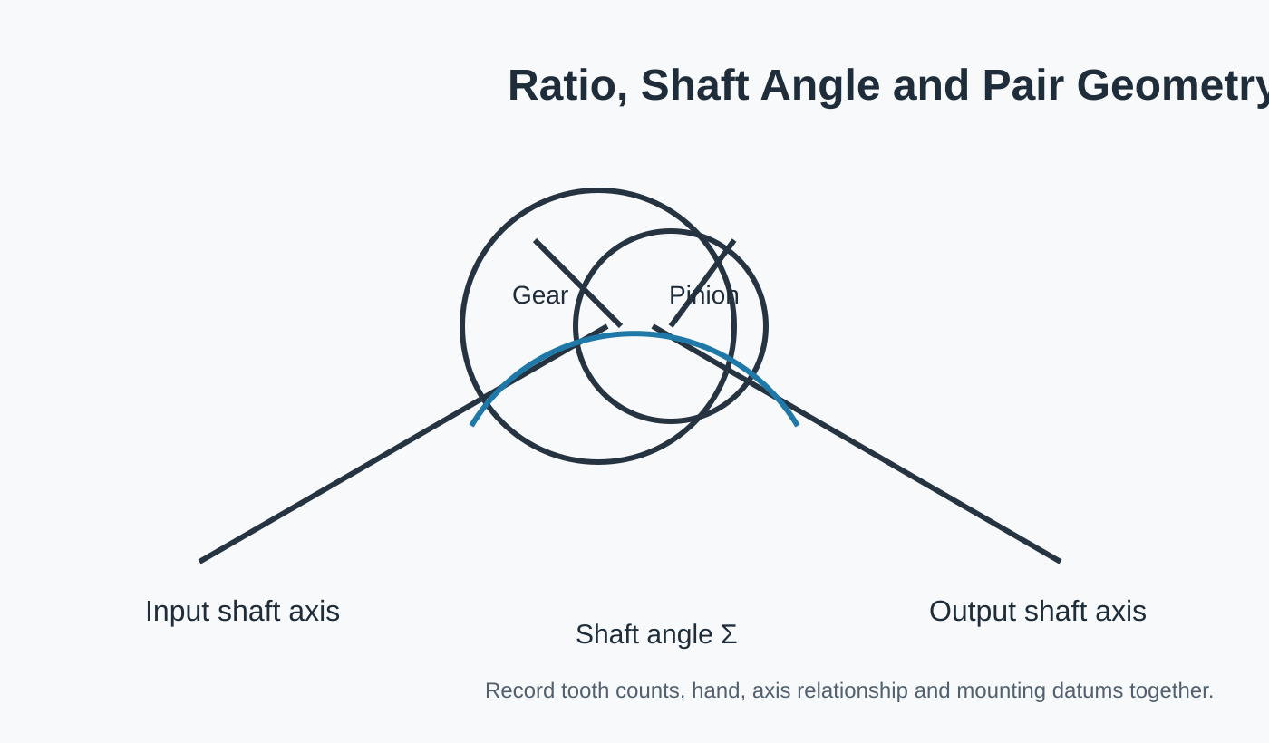
Quattro gruppi di geometria da tenere insieme
| Gruppo di geometria | Contenuto tipico | Perché è importante |
|---|---|---|
| Rapporto | Conteggio dei denti di ingranaggi e pignoni | Definisce la relazione velocità/coppia della coppia. |
| Relazione assiale | Angolo e orientamento dell'albero | Definisce il punto di intersezione dei due alberi. |
| Orientamento del dente | Mano destra/sinistra e direzione a spirale | Definisce l'orientamento del dente di accoppiamento. |
| Montaggio | Distanza di montaggio, riferimenti e gioco | Definisce la posizione degli ingranaggi all'interno dell'alloggiamento. |
La geometria di montaggio collega il disegno alla macchina
La stessa geometria dei denti può comportarsi in modo diverso se la coppia viene installata in una posizione diversa da quella prevista. Sedi dei cuscinetti, spalle e spessori possono influenzare la posizione finale. Se il gioco o il contatto sono un requisito di accettazione, il disegno e le istruzioni di montaggio devono specificare chiaramente la condizione di riferimento.
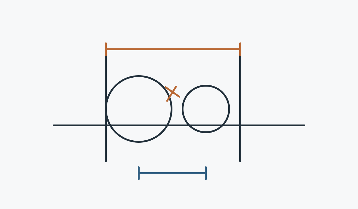
Cosa includere in una richiesta di preventivo sostitutiva
Inviare entrambi i componenti, se possibile, il numero di denti, l'orientamento di ciascun albero, i riferimenti dell'alloggiamento/cuscinetto, il gioco misurato (se affidabile) e qualsiasi disegno precedente. Se la coppia originale è molto usurata, documentare la macchina prima dello smontaggio in modo che la revisione della sostituzione possa distinguere la geometria prevista dalla condizione danneggiata.
Omissioni comuni nei disegni
A volte i disegni mostrano il numero di denti e le dimensioni esterne, ma omettono la relazione tra gli assi o il riferimento di montaggio. Altri indicano un rapporto senza specificare quale elemento sia il pignone. Queste omissioni sono gestibili in fase di progettazione, ma diventano costose quando un fornitore deve ricostruire le intenzioni a partire da diverse e-mail.
Utilizzare una vista di assieme o note chiare per collegare i due componenti. Se l'angolo dell'albero non corrisponde alla configurazione standard della macchina, assicurarsi che sia impossibile non notarlo. Se i due componenti sono di ricambio, indicare gli assi dell'alloggiamento esistente e le superfici di riferimento utilizzate per la misurazione.
Domande frequenti degli acquirenti
Il rapporto 1:1 implica automaticamente un set di ingranaggi per tagli obliqui?
Un numero uguale di denti è compatibile con una disposizione a mitra, ma è comunque necessario definire la mano, l'angolo dell'albero e la geometria di montaggio.
È possibile misurare l'angolo dell'albero a partire dalle superfici degli ingranaggi?
Quando possibile, utilizzare gli assi effettivi dell'albero o dell'alloggiamento. Le superfici degli ingranaggi potrebbero non corrispondere ai riferimenti di assemblaggio controllati.
Perché includere i dati di montaggio in un disegno della geometria del dente?
Poiché la coppia deve essere posizionata correttamente nella macchina. Le informazioni di montaggio collegano la geometria prodotta all'assemblaggio di lavoro.
Invia la coppia di ingranaggi, il disegno e le specifiche di utilizzo in un'unica richiesta di offerta.
Quanto più chiaramente vengono definiti i rapporti di accoppiamento e i riferimenti di assemblaggio, tanto più rapidamente la configurazione può essere verificata.
Guida agli ordini e alle consegne
Il quantitativo minimo d'ordine (MOQ) è flessibile in base al tipo di prodotto, al processo produttivo e al valore totale dell'ordine. Per i nuovi progetti idonei, è possibile richiedere da 1 a 5 campioni a prezzi agevolati. È possibile combinare modelli diversi quando l'importo totale dell'ordine raggiunge circa 1.500 USD. Ordini di 1 o 2 pezzi possono essere valutati, sebbene il costo unitario sia generalmente più elevato.
I tempi di pianificazione tipici sono di 10-25 giorni lavorativi per i componenti standard, 20-45 giorni lavorativi per i componenti personalizzati e 45-120 giorni lavorativi per apparecchiature o assemblaggi di tipo progettuale. Sono generalmente supportati i termini EXW, FOB, CIF e DAP; per la spedizione è possibile concordare i termini FCA, CFR, CPT, CIP e DDP.

























