
Машинний режим роботи
Поясніть частоту реверсування, прискорення, інерцію, повторюваність положення, опору вала та інтервал обслуговування. Ці дані допомагають кошторису відображати фактичну машину, а не галузеву етикетку.
У системах автоматизації використовуються приводи з пересічними осями, де герметична упаковка та можливе часте змінення напрямку руху. Зубчасту пару необхідно враховувати разом з інерцією, опорою підшипників, керованим рухом та доступом для обслуговування.
В автоматизованому обладнанні зубчаста передача рідко працює самостійно. Двигун, муфта, підшипники, вали та механізм, що знаходиться нижче за течією, впливають на те, як реверс та крутний момент відображаються на зубцях. Корисний запит цінових пропозицій описує цей профіль руху, а не розглядає шестерню як статичний елемент каталогу.
Якщо шестерня є частиною сервоприводного механізму, поясніть, чи залежить подальший процес від повторюваного кутового положення чи просто від передачі потужності. Ця відмінність впливає на те, які результати перевірки будуть корисними для покупця.
Поясніть частоту реверсування, прискорення, інерцію, повторюваність положення, опору вала та інтервал обслуговування. Ці дані допомагають кошторису відображати фактичну машину, а не галузеву етикетку.
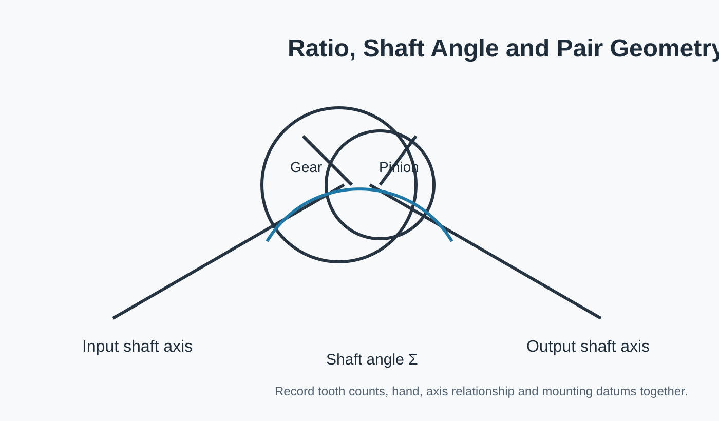
Визначте обидва елементи, кількість зубців або передавальне число, руку та який компонент приводить у рух.
Вкажіть кут вала, монтажні посилання, положення підшипників та будь-який контрольований люфт.
Вкажіть перевірку або контактні перевірки, які є важливими для випуску деталі для цієї машини.
| Область огляду | Що надати | Чому це важливо |
|---|---|---|
| Рух / чергування | Частота реверсування, прискорення, інерція, повторюваність положення, опора вала та інтервал обслуговування | Розділює постійну передачу потужності від реверсивного, ударного або залежного від положення режиму. |
| Пара шестерень | Ідентичність шестерні + шестерні, передавальне число/кількість зубців та рука | Запобігає перевірці одного компонента без його геометрії сполучення. |
| Монтаж | Розташування вала, опора підшипника, опорні точки корпусу та цільовий люфт | З'єднує виготовлену деталь з положенням, яке вона займатиме в збірці. |
| Навколишнє середовище | Контекст змащення, температури та забруднення | Підтримує практичний огляд матеріалів, обробки та обслуговування без вигадування заяв на рівні машини. |
| Інспекція | Допуски креслення, обробка зубців та необхідні записи | Визначає, що покупець використовуватиме для прийняття замовленої конфігурації. |
Люфт, прийнятний для безперервного конвеєра, може бути помітним у механізмі, який неодноразово змінює напрямок. Не припускайте типового значення люфту; використовуйте вимоги до машини та геометрію кріплення, яка фактично може його підтримувати.
Наземні або користувацькі пари є природною відправною точкою для механізмів, чутливих до руху, тоді як набір для скосу може підійти для компактних змін напрямку 1:1, коли співвідношення та відношення осей фіксовані.
Якщо роботизована вісь або комірка автоматизованого позиціонування все ще має відкриті геометрію або вхідні дані для чергування, позначте ці елементи для перегляду. Явне невідоме значення безпечніше, ніж заповнення креслення припущеним стандартним значенням.
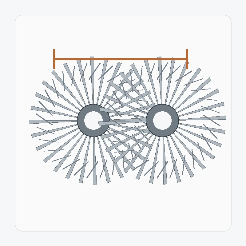
Робота із заміни спіральної конічної шестерні починається з відділення оригінальної конструктивної інформації від зносу. Пошкоджений зуб, деформований отвір або зміщений малюнок контакту можуть описувати поломку, але…
Переглянути конфігурацію →
Пару зубчастих передач зі спіральною конічною передачею для важких умов експлуатації слід перевіряти з урахуванням усіх експлуатаційних характеристик. Пікове навантаження, безперервне навантаження, ударні явища, реверси, опора підшипників та змащення – все це може мати значення…
Переглянути конфігурацію →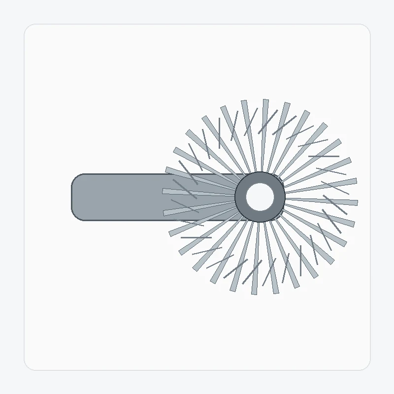
Інтеграція спіральної конічної шестерні з валом зменшує кількість окремих з'єднань, але робить опорні шипи підшипників, бурти, шліци, різьбу та опорні точки зубців частиною однієї виробничої проблеми. ...
Переглянути конфігурацію →
Спіральна торцювальна шестерня використовує однакову кількість зубців для передачі руху між валами, що перетинаються, без навмисної зміни передаточного числа швидкостей. Рівне передаточне число спрощує одну частину вибору,…
Переглянути конфігурацію →
Шліфовані спіральні конічні шестерні вимагають більше, ніж просто додавання шліфувальної операції до звичайної шестерні. Схема опорних точок, геометрія попереднього шліфування, термічна обробка, припуск на шліфування та остаточний контроль…
Переглянути конфігурацію →
Спеціальний комплект спіральних конічних шестерень будується на основі геометрії, специфічної для проекту, а не на основі загальнодоступної таблиці запасів. Корисне визначення включає обидва члени пари, вісь…
Переглянути конфігурацію →Якщо робота-вісь або автоматизована комірка позиціонування контролює матеріал або термічну обробку, вкажіть точну вимогу. Якщо ці варіанти залишаються відкритими, опишіть обов'язок та залиште вибір матеріалу/процесу для розгляду.
Фотографії роботизованої осі або автоматизованої комірки позиціонування допомагають встановити орієнтацію та стан, але вони не визначають геометрію зуба або монтажні опорні точки. Додайте сполучний елемент, дані креслення та вимірювання, взяті з контрольованих вузлів.
Для роботизованої осі або автоматизованої комірки позиціонування надішліть інформацію про збірку, яка контролює взаємозв'язок валів, монтажні опорні точки та інтерфейси. Непов'язані деталі машини можна пропустити, якщо вони не впливають на вибір передачі або перевірку.
Для роботизованої осі або автоматизованої комірки позиціонування слід відокремити кількість прототипів/зразків від очікуваного повторного попиту. Це прив'яже планування оснащення, контролю та виробництва до реального етапу закупівлі.
Чим чіткіше визначені співвідношення сполучення та дані складання, тим швидше можна переглянути конфігурацію.
Мінімальний обсяг замовлення (MOQ) залежить від типу продукту, способу виробництва та загальної вартості замовлення. Для відповідних нових проектів може знадобитися від 1 до 5 зразків за зразковою ціною. Змішані моделі можна комбінувати, коли загальна сума замовлення досягне приблизно 1500 доларів США. Замовлення від 1 до 2 штук можуть бути переглянуті, хоча вартість одиниці зазвичай вища.
Типові терміни планування становлять 10–25 робочих днів для стандартних деталей, 20–45 робочих днів для компонентів на замовлення та 45–120 робочих днів для обладнання або вузлів проектного типу. Зазвичай підтримуються умови EXW, FOB, CIF та DAP; для відвантаження можна обговорити умови FCA, CFR, CPT, CIP та DDP.