विवरण
स्पाइरल मीटर गियर सेट गति अनुपात को जानबूझकर बदले बिना प्रतिच्छेदित शाफ्टों के बीच गति संचारित करने के लिए समान दांतों की संख्या का उपयोग करता है। समान अनुपात चयन के एक भाग को सरल बनाता है, लेकिन हैंडल, शाफ्ट कोण, माउंटिंग दूरी, इंटरफेस और बैकलैश को अभी भी परिभाषित करना आवश्यक है।
सर्वोत्तम आरंभिक बिंदु: लगभग 1:1 अनुपात के साथ एक कॉम्पैक्ट प्रतिच्छेदी-अक्ष दिशा परिवर्तन और एक मेल खाने वाला सर्पिल बेवल जोड़ा।
यह उत्पाद परिवार किन समस्याओं को हल करने के लिए बनाया गया है?
माइटर गियर का उपयोग अक्सर पैकेजिंग और दिशा परिवर्तन के लिए किया जाता है। गियर सेट को एक मेल खाने वाले जोड़े के रूप में माना जाना चाहिए, खासकर जब असेंबली संपर्क या गति हानि के प्रति संवेदनशील हो।
जब डिज़ाइन में समान अनुपात आवश्यक हो, तो मीटर सेट का उपयोग करें। यदि अनुपात 1:1 नहीं है, या कोई एक भाग लंबी शाफ्ट के साथ एकीकृत है, तो इसके बजाय कस्टम या पिनियन-शाफ्ट उत्पाद परिवार का उपयोग करें।

विनिर्देश और अनुरोध तालिका
स्पाइरल मीटर गियर सेट के लिए, ऑर्डर किए गए कॉन्फ़िगरेशन के लिए सटीक संख्यात्मक मानों की पुष्टि की जाती है। नीचे दी गई तालिका उन ड्राइंग और पूछताछ क्षेत्रों को दर्शाती है जिन पर स्पष्ट नियंत्रण की आवश्यकता है।
| चयन वस्तु | विन्यास | आरएफक्यू नोट |
|---|---|---|
| जोड़ी पहचान | मेल खाने वाले स्पाइरल बेवल गियर का जोड़ा या परियोजना-विशिष्ट एकल घटक | संभोग करने वाले सदस्य और प्रेरक संबंध की पुष्टि करें। |
| शाफ्ट कोण | परियोजना विशेष | अक्षों के बीच संबंध या संयोजन आरेखण दिखाएँ। |
| अनुपात / दांतों की संख्या | ड्राइंग या आरएफक्यू के लिए | यदि दांतों की संख्या ज्ञात हो तो दोनों प्रकार की संख्या प्रदान करें। |
| मॉड्यूल / व्यास पिच | ड्राइंग या आरएफक्यू के लिए | केवल बाहरी व्यास के आधार पर अनुमान न लगाएं। |
| दबाव कोण | ऑर्डर किए गए कॉन्फ़िगरेशन की पुष्टि करें | प्रतिस्थापन कार्य के लिए ड्राइंग या विश्वसनीय पुराने डेटा का उपयोग करें। |
| सर्पिल कोण और हाथ | ऑर्डर किए गए कॉन्फ़िगरेशन की पुष्टि करें | एक निश्चित देखने की विधि का उपयोग करके दाएं/बाएं हाथ की पहचान करें। |
| माउंटिंग दूरी / बैकलैश | परियोजना विशेष | नियंत्रित होने पर आवास संबंधी डेटा और लक्ष्य सीमा प्रदान करें। |
| बोर / स्प्लाइन / शाफ्ट इंटरफ़ेस | चित्र या नमूने के लिए | इसमें कीवे, स्प्लाइन स्टैंडर्ड, जर्नल और डेटम संबंधी आवश्यकताएं शामिल करें। |
| सामग्री / ऊष्मा उपचार | ड्राइंग या प्रोजेक्ट की समीक्षा के लिए | यदि निर्धारित हो तो अनिवार्य ग्रेड, कठोरता या केस संबंधी आवश्यकताओं का उल्लेख करें। |
| दांतों की फिनिश/गुणवत्ता | ड्राइंग या प्रोजेक्ट की समीक्षा के लिए | राज्य द्वारा निर्धारित कटाई/पिसाई की आवश्यकता और स्वीकृति मानक या निरीक्षण मानदंड। |
1:1 अनुपात के लिए भी शाफ्ट के बीच एक निश्चित संबंध की आवश्यकता होती है।
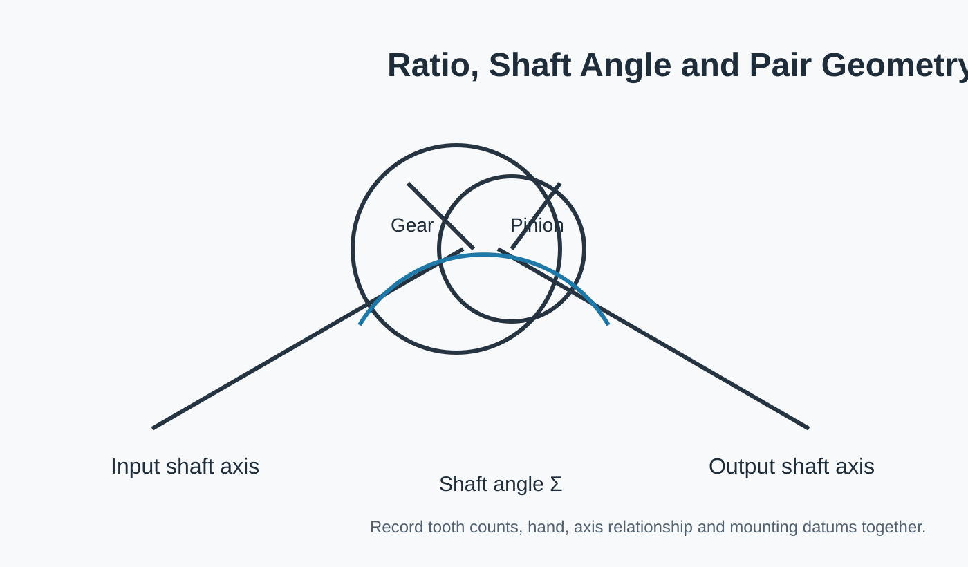
ड्राइंग में दोनों भाग, शाफ्ट का कोण और उन्हें दर्शाने वाले संदर्भ बिंदु दिखाए जाने चाहिए। यदि गियर हब, शाफ्ट या फ्लैंज में एकीकृत हैं, तो उन विशेषताओं को दांतों के संदर्भ बिंदुओं से जोड़ा जाना चाहिए। इसके बाद निर्माण और निरीक्षण, ऑर्डर की गई सामग्री और दांतों की फिनिशिंग संबंधी आवश्यकताओं के अनुसार किए जाते हैं।
स्पाइरल मीटर गियर सेट का तकनीकी दृश्य घटकों के आपसी संबंधों को समझने में सहायक होता है। नियंत्रित उत्पादन आरेख और अनुमोदित कोटेशन ही ऑर्डर के लिए आयामी परिभाषा बने रहते हैं।
इंटरफेस और असेंबली जांच

संभोग सदस्य
पुष्टि करें कि कौन सा गियर घटक के साथ मेल खाता है और क्या आपूर्ति में दोनों भाग शामिल हैं।

डेटम और माउंटिंग
माउंटिंग दूरी, शाफ्ट की स्थिति और बैकलैश को नियंत्रित करने वाली सतहों और अक्षों को दर्शाइए।

सामग्री मार्ग
राज्य नियंत्रित सामग्री/ऊष्मा उपचार संबंधी आवश्यकताओं का निर्धारण करें और उन विशेषताओं की पहचान करें जिन्हें द्वितीयक मशीनिंग की आवश्यकता है।

स्वीकार
रिलीज़ के लिए आवश्यक आयामी, दांत की गुणवत्ता, रनआउट या संपर्क जांचों की सूची बनाएं।
विशिष्ट अनुप्रयोग उपयुक्तता
समकोण सहायक ड्राइव, कॉम्पैक्ट मशीन तंत्र, स्वचालन उपकरण और गियरबॉक्स जहां समान अनुपात और प्रतिच्छेदी अक्षों की आवश्यकता होती है।
सामग्री के मार्ग, दांतों की फिनिशिंग, सपोर्ट संबंधी मान्यताओं या निरीक्षण संबंधी आवश्यकताओं में बदलाव होने की संभावना होने पर आवेदन पत्र को ड्राइंग के साथ भेजा जाना चाहिए।

सीएनसी मशीन टूल्स

समकोण ड्राइव और पोजिशनिंग तंत्र जहां माउंटिंग कठोरता और बैकलैश मायने रखते हैं।
आवेदन संबंधी दिशानिर्देश →
रोबोटिक्स और स्वचालन

विपरीत दिशा में कार्य करने और दोहराव की आवश्यकताओं वाले कॉम्पैक्ट प्रतिच्छेदी अक्ष तंत्र।
आवेदन संबंधी दिशानिर्देश →
लेजर कटिंग और गैन्ट्री सिस्टम

गैन्ट्री और स्वचालित स्थिति निर्धारण उपकरणों के आसपास दिशा-परिवर्तन संचरण।
आवेदन संबंधी दिशानिर्देश →
भारी सामान उठाना और उठाना

ऐसे भारी-भरकम यंत्र जिनमें झटके, चालू/बंद होने की व्यवस्था और सहारा देने की व्यवस्था की समीक्षा की आवश्यकता होती है।
आवेदन संबंधी दिशानिर्देश →
सटीक मशीनरी

नियंत्रित डेटम, रनआउट और संपर्क आवश्यकताओं के साथ कॉम्पैक्ट परिशुद्धता प्रणालियाँ।
आवेदन संबंधी दिशानिर्देश →
औद्योगिक गियरबॉक्स

गियरबॉक्स के वे चरण जो प्रतिच्छेदी शाफ्ट व्यवस्थाओं के माध्यम से टॉर्क को प्रवाहित करते हैं।
आवेदन संबंधी दिशानिर्देश →विनिर्माण और निरीक्षण अनुक्रम
समीक्षा
ड्राइंग संशोधन, जोड़ी पहचान, खुले प्रश्न और स्वीकृति-संबंधी महत्वपूर्ण विशेषताओं की पुष्टि करें।
योजना
ब्लैंक, डेटम मशीनिंग, गियर कटिंग, हीट ट्रीटमेंट और फिनिश सीक्वेंस को परिभाषित करें।
खत्म करना
निर्धारित प्रक्रिया के अनुसार दांत और इंटरफ़ेस की संपूर्ण फिनिशिंग।
निरीक्षण करें
कॉन्फ़िगरेशन के लिए सहमत आयामों और गियर से संबंधित मानदंडों की जाँच करें।
पूछताछ में क्या-क्या शामिल करना है
| आरएफक्यू समूह | अनुशंसित विवरण |
|---|---|
| तकनीकी परिभाषा | वर्तमान रेखाचित्र, युग्म संदर्भ, अनुपात/दांतों की संख्या, हाथ और अक्ष संबंध |
| विधानसभा | यदि नियंत्रित हो तो बोर/शाफ़्ट/स्प्लाइन, बियरिंग, हाउसिंग डेटम, माउंटिंग दूरी और बैकलैश। |
| कर्तव्य | गति, टॉर्क/लोड स्पेक्ट्रम, उलटफेर, झटके, पर्यावरण और स्नेहन |
| गुणवत्ता | सामग्री, ताप उपचार, दांतों की फिनिशिंग, सहनशीलता और निरीक्षण संबंधी रिकॉर्ड |
| व्यावसायिक | प्रोटोटाइप और दोहराव की मात्रा, गंतव्य, समय सीमा और पसंदीदा व्यापार शर्तें |
अक्सर पूछे जाने वाले प्रश्नों
क्या मैं इस जोड़ी में से केवल एक ही सदस्य का ऑर्डर दे सकता हूँ?
स्पाइरल मीटर गियर सेट के लिए, जब मेट पूरी तरह से परिभाषित हो जाए, तभी एक सदस्य की आपूर्ति की समीक्षा की जा सकती है। यदि मौजूदा मेट अज्ञात है, तो किसी भी घटक को जारी करने से पहले उसका चित्र, माप या वास्तविक गियर भेजें।
क्या घिसे-पिटे नमूने की सीधी नकल बनाई जा सकती है?
घिसे हुए स्पाइरल मीटर गियर सेट का नमूना पहचान में सहायक हो सकता है, लेकिन घिसावट को मूल ज्यामिति नहीं माना जाना चाहिए। पुराने चित्र, अप्रयुक्त मिलान भाग और असेंबली माप एक मजबूत पुनर्निर्माण आधार प्रदान करते हैं।
क्या मुझे आरएफक्यू भेजने से पहले सामग्री और हीट ट्रीटमेंट का चयन करना होगा?
जब स्पाइरल मीटर गियर सेट का डिज़ाइन सामग्री या ऊष्मा उपचार को नियंत्रित करता हो, तो सटीक आवश्यकता बताएं। यदि ये आइटम खुले हैं, तो उनका कार्य विवरण दें और उन्हें चयन समीक्षा के लिए चिह्नित करें, न कि किसी अन्य गियर से ग्रेड उधार लें।
कम मात्रा में नमूनों को कैसे संभाला जाता है?
स्पाइरल मीटर गियर सेट के छोटे नमूनों की समीक्षा करके उपयुक्त नई परियोजनाओं का चयन किया जा सकता है। प्रोटोटाइप की मात्रा को अपेक्षित पुन: मांग से अलग रखें ताकि सेटअप, निरीक्षण और बाद में उत्पादन की योजना सही मात्रा के अनुसार बनाई जा सके।
आपके आरएफक्यू के लिए व्यावसायिक योजना
कोटेशन अनुरोध योजना के लिए, न्यूनतम ऑर्डर मात्रा (MOQ) लचीली है और उत्पाद के प्रकार, प्रसंस्करण प्रक्रिया और कुल ऑर्डर मूल्य पर निर्भर करती है। उपयुक्त नए प्रोजेक्ट्स के लिए 1-5 सैंपल पीस सैंपल मूल्य पर उपलब्ध कराए जा सकते हैं। लगभग 1,500 अमेरिकी डॉलर के कुल ऑर्डर पर विभिन्न मॉडलों को संयोजित किया जा सकता है। 1-2 पीस के ऑर्डर पर भी विचार किया जा सकता है, आमतौर पर इनकी प्रति यूनिट लागत अधिक होती है क्योंकि सेटअप और निरीक्षण बहुत कम मात्रा में किए जाते हैं।
कोटेशन अनुरोध के लिए डिलीवरी योजना में, मानक पुर्जों के लिए आमतौर पर 10-25 कार्यदिवस, अनुकूलित घटकों के लिए 20-45 कार्यदिवस और परियोजना-प्रकार के उपकरण या असेंबली के लिए 45-120 कार्यदिवस का समय लगता है। EXW, FOB, CIF और DAP आमतौर पर स्वीकार्य हैं; FCA, CFR, CPT, CIP और DDP पर विशिष्ट शिपमेंट और गंतव्य के लिए चर्चा की जा सकती है।
गियर पेयर, ड्राइंग और ड्यूटी की जानकारी एक ही आरएफक्यू में भेजें।
मिलान संबंध और संयोजन तिथियों को जितनी स्पष्ट रूप से परिभाषित किया जाएगा, उतनी ही तेजी से विन्यास की समीक्षा की जा सकेगी।
ऑर्डर और डिलीवरी संबंधी मार्गदर्शन
उत्पाद के प्रकार, निर्माण प्रक्रिया और कुल ऑर्डर मूल्य के आधार पर न्यूनतम ऑर्डर मात्रा (MOQ) लचीली है। उपयुक्त नए प्रोजेक्ट के लिए नमूना मूल्य पर 1-5 नमूना पीस मंगवाए जा सकते हैं। लगभग 1,500 अमेरिकी डॉलर के कुल ऑर्डर पर मिश्रित मॉडल का ऑर्डर दिया जा सकता है। 1-2 पीस के ऑर्डर पर भी विचार किया जा सकता है, हालांकि प्रति यूनिट लागत आमतौर पर अधिक होती है।
मानक पुर्जों के लिए सामान्य योजना अवधि 10-25 कार्यदिवस, अनुकूलित घटकों के लिए 20-45 कार्यदिवस और परियोजना-प्रकार के उपकरण या असेंबली के लिए 45-120 कार्यदिवस होती है। EXW, FOB, CIF और DAP आमतौर पर स्वीकार्य हैं; शिपमेंट के लिए FCA, CFR, CPT, CIP और DDP पर चर्चा की जा सकती है।

























