
Maskinplikt
Forklar repeterbarhet, lav tapt bevegelse, akseljustering, termisk oppførsel, lagerforspenning, smøring og inspeksjonsomfang. Disse inndataene bidrar til at tilbudet gjenspeiler den faktiske maskinen i stedet for en bransjeetikett.
Presisjonsmaskiner har en tendens til å gjøre små monteringsfeil mer synlige. Anbudsforespørselen bør koble tanngeometri med referanser, lagerstøtte, forventet klaring og inspeksjonsresultatene som trengs for å frigi delen.

Et presist girpar avhenger fortsatt av maskinstrukturen som plasserer det. Hvis huset eller lagerbunken flytter giret bort fra den tiltenkte monteringsavstanden, kan tannkontakten forskyve seg selv når begge girene er laget i henhold til tegningen.
Når et prosjekt har temperaturfølsom oppførsel, inkluder driftsområdet og materialene rundt girparet. Ikke gjør denne konteksten om til en ytelsespåstand på produktnivå med mindre den bestilte konfigurasjonen har blitt evaluert for den.
Forklar repeterbarhet, lav tapt bevegelse, akseljustering, termisk oppførsel, lagerforspenning, smøring og inspeksjonsomfang. Disse inndataene bidrar til at tilbudet gjenspeiler den faktiske maskinen i stedet for en bransjeetikett.
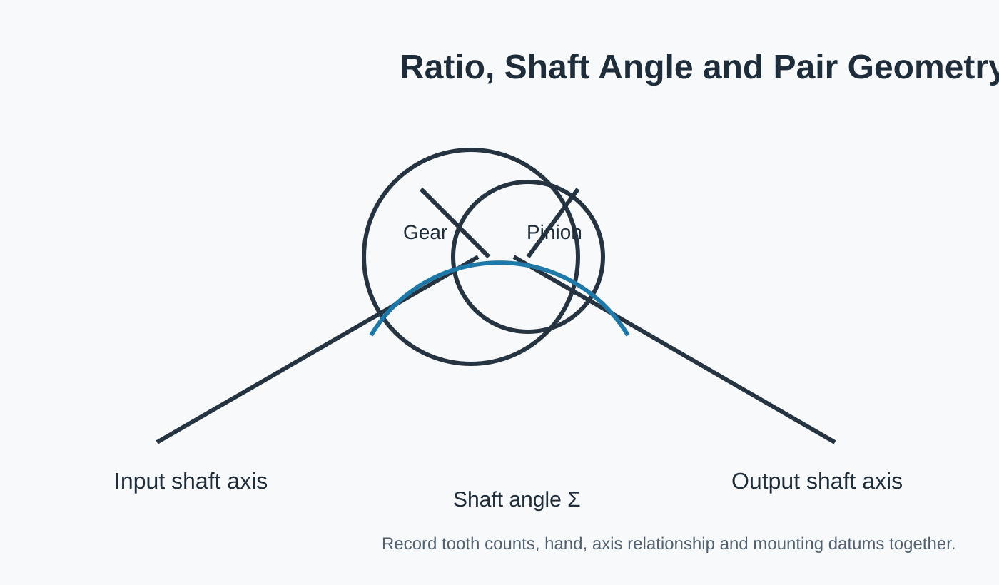
Identifiser begge medlemmene, tanntall eller forholdstall, hånd og hvilken komponent som driver.
Vis akselvinkel, monteringsreferanser, lagerposisjoner og eventuelt kontrollert slakk.
Oppgi inspeksjonen eller kontaktkontrollene som er viktige for å frigi delen til denne maskinen.
| Gjennomgangsområde | Hva som skal gis | Hvorfor det er viktig |
|---|---|---|
| Bevegelse / plikt | Repeterbarhet, lav tapt bevegelse, akseljustering, termisk oppførsel, lagerforspenning, smøring og inspeksjonsomfang | Skiller jevn kraftoverføring fra rygging, støt eller posisjonssensitiv drift. |
| Girpar | Gir + pinjongidentitet, utveksling/tanntall og hånd | Forhindrer at én komponent blir gjennomgått uten sin paringsgeometri. |
| Montering | Akselarrangement, lagerstøtte, husnullpunkter og målslark | Kobler den produserte delen til posisjonen den skal holde i monteringen. |
| Miljø | Smøring, temperatur og kontamineringskontekst | Støtter praktisk gjennomgang av materialer, finish og service uten å finne på påstander på maskinnivå. |
| Undersøkelse | Tegningstoleranser, tannfinish og nødvendige dokumenter | Definerer hva kjøperen skal bruke for å godta den bestilte konfigurasjonen. |
Strammere tall er ikke automatisk bedre hvis maskinen ikke kan holde dem. Definer verdiene som monteringen kan kontrollere, og angi hvilken overflate eller akse som er referansen for hver akseptdimensjon.
Jordede eller spesialtilpassede par er typiske utgangspunkt for applikasjoner med høyere kontroll. En pinjongaksel kan redusere separate leddgrensesnitt når designet bevisst integrerer akselen og pinjongen.
Hvis en presisjonsmaskinmontering fortsatt har åpne geometri- eller driftsinndata, merk disse elementene for gjennomgang. En eksplisitt ukjent er tryggere enn å fylle tegningen med en antatt standardverdi.
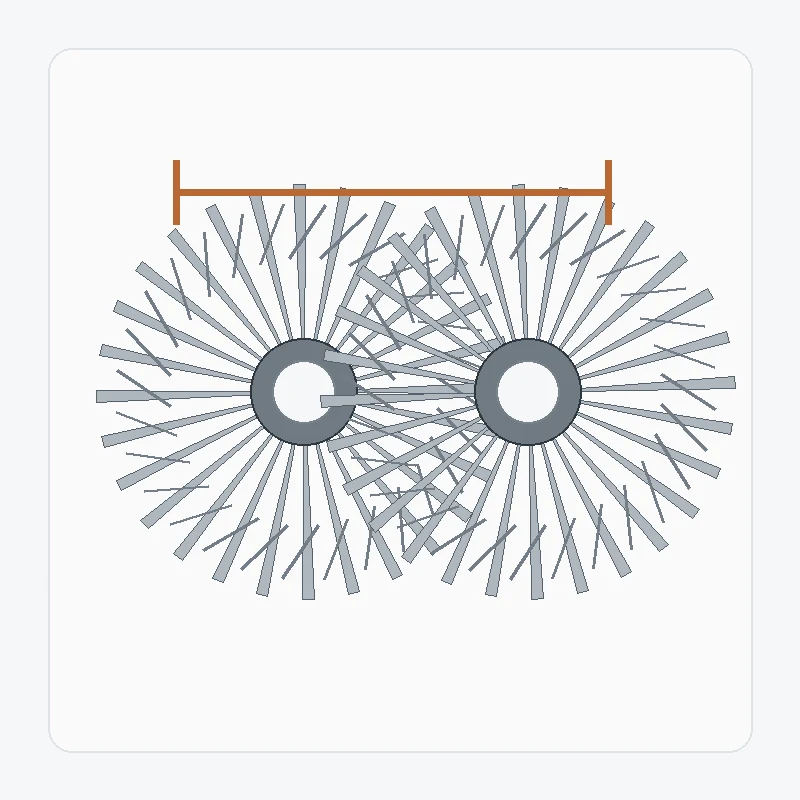
Arbeidet med å bytte ut spiralformede koniske gir starter med å skille original designinformasjon fra slitasje. En skadet tann, forvrengt boring eller forskjøvet kontaktmønster kan forklare feilen, men…
Vis konfigurasjon →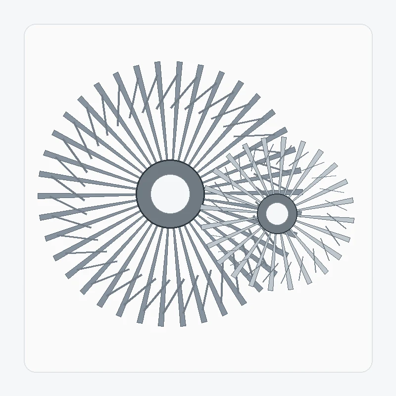
Et kraftig spiralformet konisk girpar bør vurderes ut fra hele driftsoppgaven. Toppbelastning, kontinuerlig belastning, sjokkhendelser, reverseringer, lagerstøtte og smøring kan alle ha betydning ...
Vis konfigurasjon →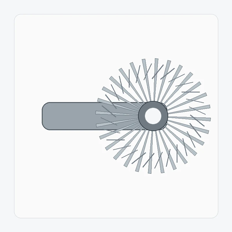
Integrering av spiralformet konisk tannhjul med en aksel reduserer separate ledd, men det gjør lagertapper, skuldre, riller, gjenger og tanndata til en del av ett produksjonsproblem. ...
Vis konfigurasjon →
Et spiralformet gjæringsgirsett bruker like mange tenner for å overføre bevegelse mellom kryssende aksler uten å endre hastighetsforholdet med vilje. Likt forhold forenkler én del av valget,…
Vis konfigurasjon →
Slipte spiralformede koniske gir krever mer enn å legge til en slipeoperasjon til et vanlig gir. Nullpunktskjemaet, forslipingsgeometrien, varmebehandlingen, slipetillegget og den endelige inspeksjonen har…
Vis konfigurasjon →
Et spesialtilpasset spiralformet konisk girsett er bygget rundt prosjektspesifikk geometri i stedet for en offentlig lagertabell. Den nyttige definisjonen inkluderer begge medlemmene av paret, aksen ...
Vis konfigurasjon →Når presisjonsmaskinens monteringstegninger kontrollerer materiale eller varmebehandling, inkluder det nøyaktige kravet. Hvis disse valgene fortsatt er åpne, beskriv oppgaven og la material-/prosessvalget være til gjennomgang.
Bilder av presisjonsmaskinmonteringen hjelper med å fastslå retning og tilstand, men de definerer ikke tanngeometri eller monteringsdata. Legg til motstykket, tegningsdata og målinger tatt fra kontrollerte monteringsreferanser.
For presisjonsmaskinmontering, send monteringsinformasjonen som styrer akselforhold, monteringsdatum og grensesnitt. Irrelaterte maskindetaljer kan utelates når de ikke har noen effekt på girvalg eller inspeksjon.
For presisjonsmaskinmontering, separer prototype-/prøvemengden fra forventet gjentatt etterspørsel. Dette holder verktøy, inspeksjon og produksjonsplanlegging knyttet til den faktiske innkjøpsfasen.
Jo tydeligere paringsforholdet og monteringsdatumene er definert, desto raskere kan konfigurasjonen gjennomgås.
MOQ er fleksibel avhengig av produkttype, produksjonsrute og total ordreverdi. Egnede nye prosjekter kan be om 1–5 prøvestykker til prøvepris. Blandede modeller kan kombineres når den totale ordresummen når omtrent USD 1500. Bestillinger på 1–2 stykker kan vurderes, selv om enhetskostnaden vanligvis er høyere.
Typiske planleggingsvinduer er 10–25 virkedager for standarddeler, 20–45 virkedager for tilpassede komponenter og 45–120 virkedager for prosjektutstyr eller sammenstillinger. EXW, FOB, CIF og DAP støttes vanligvis; FCA, CFR, CPT, CIP og DDP kan diskuteres for forsendelsen.