Схема контакту зубів може бути корисним вікном у те, як зустрічається пара спіральних скошених зубів, але сама по собі вона не є повною діагностикою. Схема залежить від геометрії пари, положення монтажу, навантаження, методу перевірки та стану корпусу та підшипників. Тому корисний протокол перевірки вказує, як була отримана схема, а не лише як вона виглядала.
Положення контакту слід обговорити з урахуванням умов перевірки
Зразок, який виглядає центрованим під одним методом перевірки за невеликого навантаження, може зміщуватися під робочим навантаженням або при зміні монтажного положення. Зміщення носка/п'яти та лицьової/кореневої поверхні можуть бути корисними спостереженнями, але їх слід інтерпретувати відповідно до креслення, монтажної відстані та зазначеної процедури перевірки.
Це особливо важливо під час заміни, де зношені підшипники або деформований корпус можуть змінити схему роботи незалежно від нової геометрії шестерні.
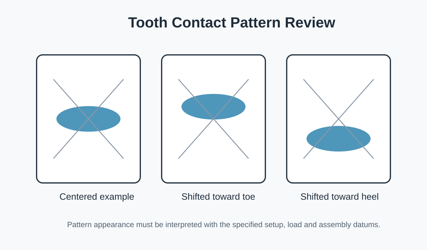
Інформація для запису за допомогою шаблону
| Запис | Чому це важливо |
|---|---|
| Який учасник керує | Контакт може обговорюватися по-різному залежно від напрямку руху. |
| Напрямок обертання | Реверсивне оброблення може навантажувати різні поверхні зубів. |
| Перевірка навантаження / методу | Перевірка світлової маркування та діаграма робочого навантаження – це не одне й те саме. |
| Положення монтажу | Монтажна відстань, прокладки та стан підшипника впливають на результат. |
| Зворотна реакція | Стан складання слід зафіксувати за допомогою перевірки контактів. |
| Парна ідентичність | Результат належить до конкретної шестерні та шестерні, що перевіряються. |
Використовуйте перевірку контактів як частину ширшого плану перевірки
Перевірка розмірів та якості зубів повідомляє покупцеві, чи відповідають окремі компоненти контрольованим вимогам. Контактний огляд додає інформацію про те, як пара працює разом у визначеній конфігурації. Обидва методи корисніші, коли з самого початку задокументовані однакові дані та припущення щодо складання.
Що закономірність не може довести сама по собі
Сам по собі малюнок контакту не доводить якість матеріалу, термічну обробку, точність зуба, стан підшипника або довгострокову експлуатацію. Його не слід використовувати для перетворення невідомого зразка для заміни на точне технічне твердження. Використовуйте його як один із доказів у контрольованому огляді пари та вузла.
Практичний контрольний список для перевірки контактів
Перш ніж порівнювати шаблони, переконайтеся, що використовується та сама пара, напрямок обертання, положення монтажу, люфт та метод перевірки. Сфотографуйте позначені зубці з достатнім контекстом, щоб ідентифікувати шестерню та орієнтацію. Якщо було проведено регулювання, запишіть, що змінилося, перш ніж робити наступне зображення.
Ця послідовність перетворює шаблон на корисний запис перевірки. Без інформації про налаштування два зображення можуть виглядати по-різному з причин, які не мають нічого спільного з виробництвом зубів.
Питання, які часто ставлять покупці
Чи завжди центрований візерунок правильний?
Не саме по собі. Прийнятне місце розташування залежить від проекту, методу перевірки та заданих умов. Використовуйте вимоги до перевірки проекту, а не загальне фото.
Чи може контактна схема діагностувати несправний підшипник?
Це може показати, що положення пари змінилося, але само по собі не визначає причину. Стан підшипника, корпусу, кріплення та геометрію шестерні необхідно перевіряти разом.
Чи слід включати перевірку контактів до кожного замовлення?
Включіть його, якщо це є частиною креслення, плану приймання або вимог проекту. Не додавайте випробування лише як прикрасу, якщо це не допоможе покупцю випустити деталь.
Надішліть зубчасту пару, креслення та характеристики в одному запиті цінової пропозиції.
Чим чіткіше визначені співвідношення сполучення та дані складання, тим швидше можна переглянути конфігурацію.
Інструкції щодо замовлення та доставки
Мінімальний обсяг замовлення (MOQ) залежить від типу продукту, способу виробництва та загальної вартості замовлення. Для відповідних нових проектів може знадобитися від 1 до 5 зразків за зразковою ціною. Змішані моделі можна комбінувати, коли загальна сума замовлення досягне приблизно 1500 доларів США. Замовлення від 1 до 2 штук можуть бути переглянуті, хоча вартість одиниці зазвичай вища.
Типові терміни планування становлять 10–25 робочих днів для стандартних деталей, 20–45 робочих днів для компонентів на замовлення та 45–120 робочих днів для обладнання або вузлів проектного типу. Зазвичай підтримуються умови EXW, FOB, CIF та DAP; для відвантаження можна обговорити умови FCA, CFR, CPT, CIP та DDP.

























