Replacement Spiral Bevel Gear Set
Replacement spiral bevel gear work begins by separating original design information from service wear. A damaged tooth, distorted bore or shifted contact pattern can describe the failure, but…
View configuration →Specify the gear pair, shaft relationship, mounting datums and duty as one system. EVER POWER supports new designs and replacement work where the practical job is not simply cutting teeth, but obtaining the correct contact, interfaces and assembly relationship for the application.

Start with the form of the component and the level of tooth finishing you need. Product pages below are configuration families, not invented stock sizes; final geometry is confirmed against the ordered drawing, sample or RFQ data.
Replacement spiral bevel gear work begins by separating original design information from service wear. A damaged tooth, distorted bore or shifted contact pattern can describe the failure, but…
View configuration →
A heavy-duty spiral bevel gear pair should be reviewed from the complete operating duty. Peak load, continuous load, shock events, reversals, bearing support and lubrication can all matter…
View configuration →
Integrating the spiral bevel pinion with a shaft reduces separate joints, but it makes bearing journals, shoulders, splines, threads and tooth datums part of one manufacturing problem. The…
View configuration →
A spiral miter gear set uses equal tooth counts to transmit motion between intersecting shafts without intentionally changing speed ratio. Equal ratio simplifies one part of the selection,…
View configuration →
Ground spiral bevel gears require more than adding a grinding operation to a normal gear. The datum scheme, pre-grind geometry, heat treatment, grinding allowance and final inspection have…
View configuration →
A custom spiral bevel gear set is built around project-specific geometry rather than a public stock table. The useful definition includes both members of the pair, the axis…
View configuration →For an intersecting-axis transmission, tooth count is only one piece of the decision. The pair also needs the correct hand, shaft angle, mounting distance, bore or shaft interface, and backlash target. Replacement enquiries are much faster when the mating member and housing datums are identified at the same time.
Use the RFQ path to send the pair information in one package. It reduces the chance that a visually similar gear is quoted against the wrong geometry.
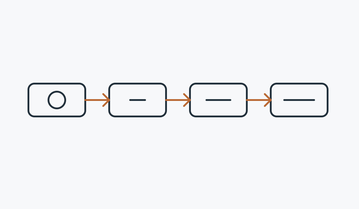
Confirm which member drives, which member mates, right/left hand and whether both components are being supplied.
Identify shaft angle, mounting distance, backlash and the assembly datums that control tooth contact.
Match material, heat treatment and tooth finishing to duty, wear requirements and drawing callouts.
State the gear quality standard, contact inspection, runout or dimensional records expected with the order.
They are useful when torque must turn through an intersecting-axis arrangement while the assembly still needs controlled contact, compact packaging and predictable positioning.
Right-angle drives and positioning mechanisms where mounting stiffness and backlash matter.
Application guidance →
Compact intersecting-axis mechanisms with reversing duty and repeatability requirements.
Application guidance →
Direction-changing transmission around gantries and automated positioning equipment.
Application guidance →
Heavy-duty mechanisms where shock, starts/stops and support arrangement need review.
Application guidance →
Compact precision systems with controlled datums, runout and contact requirements.
Application guidance →
Gearbox stages that route torque through intersecting shaft arrangements.
Application guidance →Blank preparation, turning, gear cutting, heat treatment, finishing and inspection should be considered as one route because each step can affect the final datum relationship. For ground configurations, the sequence must protect the references used to locate the gear during tooth finishing and final checks.
RFQs from Germany, Japan, Switzerland, Italy and the United States often arrive with different drawing conventions and documentation expectations, but the technical basis is the same: identify the pair, datums, duty and acceptance criteria before quoting.
The more clearly the mating relationship and assembly datums are defined, the faster the configuration can be reviewed.
MOQ is flexible by product type, manufacturing route and total order value. Suitable new projects may request 1–5 sample pieces at sample pricing. Mixed models can be combined when the order total reaches approximately USD 1,500. Orders of 1–2 pieces can be reviewed, although unit cost is normally higher.
Typical planning windows are 10–25 working days for standard parts, 20–45 working days for customized components and 45–120 working days for project-type equipment or assemblies. EXW, FOB, CIF and DAP are commonly supported; FCA, CFR, CPT, CIP and DDP can be discussed for the shipment.