Описание
Комплект конических зубчатых передач со спиральной зубчатой передачей изготавливается на основе геометрии, специфичной для конкретного проекта, а не по общедоступной таблице стандартных параметров. Полезное описание включает в себя оба элемента пары, соотношение осей, данные о зубьях, точки крепления, интерфейсы и фактически контролируемые требования к производству/контролю качества.
Лучшая отправная точка: Новая или контролируемая конструкция, в которой на чертежах могут быть определены как элементы конструкции, так и расположение валов, а также критерии приемки.
Для решения каких задач предназначена данная линейка продуктов?
Эта конфигурация представляет собой наиболее широкую отправную точку, когда геометрия является неотъемлемой частью чертежа. Она может поддерживать необычные соотношения, интерфейсы или компоновку, но каждая дополнительная степень свободы делает контроль над чертежом еще более важным.
Выберите эту страницу, если геометрия уникальна или еще не привязана к старому образцу. Если поверхность зубьев специально отшлифована, страница «Шлифованный комплект спиральных конических зубчатых передач» содержит более подробное описание процесса.

Таблица технических характеристик и запроса предложений
Для комплектов конических зубчатых передач с винтовой передачей, изготовленных на заказ, точные числовые значения подтверждаются для заказанной конфигурации. В таблице ниже указаны поля чертежа и запроса, требующие явного контроля.
| Выбранный элемент | Конфигурация | Примечание к запросу предложений |
|---|---|---|
| Идентичность пары | Подобранная пара конических зубчатых передач или отдельный компонент, разработанный специально для данного проекта. | Подтвердите родственные отношения между супругом и водителем. |
| Угол наклона вала | Проектно-специфический | Покажите соотношение осей или сборочный чертеж. |
| Соотношение / количество зубов | К чертежу или запросу коммерческого предложения | Укажите количество зубов в обеих группах, если оно известно. |
| Модуль / диаметральный шаг | К чертежу или запросу коммерческого предложения | Не следует оценивать диаметр только по внешнему диаметру. |
| Угол давления | Подтвердите заказанную конфигурацию. | Для проведения работ по замене используйте чертеж или достоверные архивные данные. |
| Спиральный угол и рука | Подтвердите заказанную конфигурацию. | Определите правую/левую руку, используя установленную систему обозначений. |
| Расстояние между крепежными отверстиями / люфт | Проектно-специфический | При наличии контроля необходимо указать базовые параметры здания и дальность стрельбы. |
| Соединение отверстия/шлица/вала | К чертежу или образцу | Укажите требования к шпоночному пазу, стандарту шлицевого соединения, шейкам и базовой плоскости. |
| Материал / термообработка | На рассмотрение чертежей или проектов. | Укажите обязательные требования к сорту, твердости или толщине покрытия, если таковые имеются. |
| Качество обработки поверхности зуба | На рассмотрение чертежей или проектов. | Требования к качеству вырубки/обработки грунта, установленные государством, а также стандарты приемки или критерии проверки. |
Определим эту пару как единую систему.
Технологический процесс изготовления выбирается на основе чертежа. Обработка заготовки и базовых точек должна обеспечить стабильные ориентиры для нарезания зубьев и последующей чистовой обработки. Затем планируется термообработка и чистовая обработка зубьев, чтобы при окончательной проверке использовались одни и те же контролируемые базовые точки.
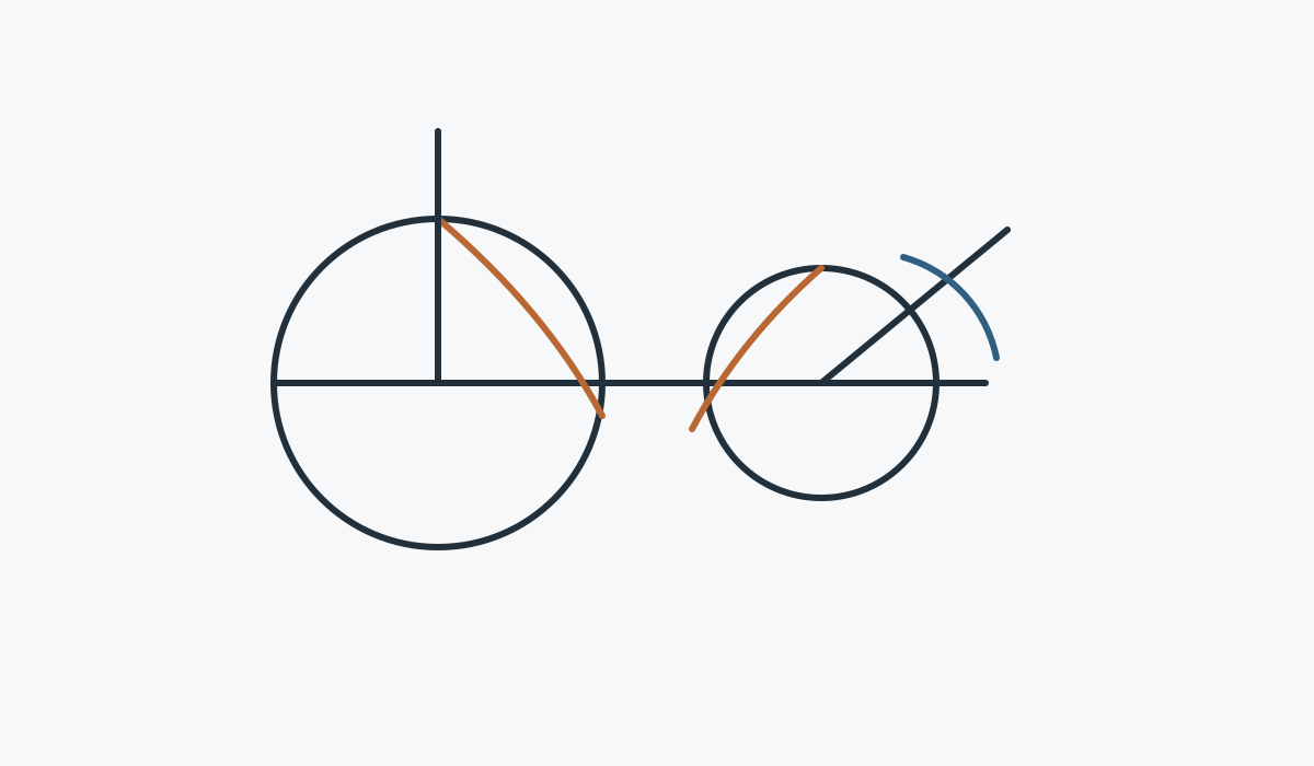
Техническое изображение комплекта конических зубчатых передач с винтовой передачей, изготовленного на заказ, служит вспомогательным средством для обсуждения взаимосвязей компонентов. Размеры для заказа определяются на основе утвержденного производственного чертежа и коммерческого предложения.
Проверка интерфейсов и сборок.

Брачный член
Уточните, какая шестерня подходит к компоненту и входят ли оба элемента в комплект поставки.

Базовые точки и крепление
Покажите поверхности и оси, которые определяют расстояние между крепежными элементами, положение вала и люфт.

Маршрут поставки материалов
Укажите требования к контролируемым материалам/термообработке и определите элементы, требующие дополнительной механической обработки.

Принятие
Перечислите необходимые для выпуска изделия проверки размеров, качества зубьев, биения или контакта.
Типичное применение
Новое оборудование, компактные угловые приводы, специальные редукторы, механизмы автоматизации и любые узлы, для которых согласованная пара определяется чертежом.
Описание требований к применению должно прилагаться к чертежу, если оно может изменить способ подачи материала, обработку зубьев, опорные допущения или требования к контролю качества.
Станки с ЧПУ

Приводы и механизмы позиционирования с прямым углом наклона, где важны жесткость крепления и люфт.
Инструкция по применению →
Робототехника и автоматизация

Компактные механизмы с пересекающимися осями, отвечающие требованиям к реверсивному режиму работы и повторяемости.
Инструкция по применению →
Системы лазерной резки и портальные системы

Передача данных с изменением направления движения вокруг портальных конструкций и автоматизированного позиционирующего оборудования.
Инструкция по применению →
Подъем тяжелых грузов и лебедки

Механизмы повышенной прочности, требующие проверки на ударопрочность, пуск/остановка и конструкция опоры.
Инструкция по применению →
Прецизионное машиностроение

Компактные прецизионные системы с контролируемыми базовыми элементами, биением и контактными требованиями.
Инструкция по применению →
Промышленные редукторы

Секции редуктора, передающие крутящий момент через пересекающиеся валы.
Инструкция по применению →Последовательность изготовления и контроля
Обзор
Подтвердите правки чертежа, идентификацию пар, открытые вопросы и критически важные для приемки элементы.
План
Определите последовательность операций: обработка заготовки, базовая обработка, нарезка зубьев, термообработка и чистовая обработка.
Заканчивать
Завершите чистовую обработку зуба и межфазной границы в соответствии с заданным маршрутом.
Осмотреть
Проверьте размеры и параметры, касающиеся оборудования, согласованные для данной конфигурации.
Что следует включить в запрос?
| Группа RFQ | Рекомендуемая детализация |
|---|---|
| Техническое определение | Текущий чертеж, парные ссылки, соотношение/количество зубьев, ориентация и соотношение осей. |
| Сборка | Диаметр цилиндра/вала/шлицевого соединения, подшипники, базовые точки корпуса, монтажное расстояние и люфт (если контролируется). |
| Долг | Скорость, крутящий момент/спектр нагрузки, реверсы, удары, окружающая среда и смазка. |
| Качество | Материал, термообработка, качество обработки поверхности зубьев, допуски и протоколы контроля. |
| Коммерческий | Типы прототипов и для повторного производства, место назначения, целевые сроки и предпочтительные условия торговли. |
Часто задаваемые вопросы
Могу ли я заказать только один элемент из пары?
Для изготовления конических зубчатых передач по индивидуальному заказу, поставку одного элемента можно пересмотреть после того, как будет полностью определена сопряженная деталь. Если существующая сопряженная деталь неизвестна, перед выпуском отдельного компонента следует отправить ее чертеж, размеры или саму зубчатую передачу.
Можно ли напрямую скопировать изношенный образец?
Образец изношенной зубчатой передачи с коническими зубьями, изготовленной на заказ, может помочь в идентификации, но износ не следует рассматривать как первоначальную геометрию. Старые чертежи, неиспользованный сопрягаемый элемент и измерения сборки обеспечивают более надежную основу для реконструкции.
Нужно ли мне выбирать материал и термообработку до отправки запроса на коммерческое предложение?
Если конструкция зубчатой передачи со спиральными коническими шестернями определяет материал или термообработку, укажите точные требования. Если эти параметры не определены, опишите режим работы и отметьте их для последующего выбора, а не заимствования марки шестерни у другой модели.
Как осуществляется обработка небольших объемов образцов?
Небольшие образцы комплектов конических зубчатых передач со спиральной зубчатой передачей, изготовленных на заказ, могут быть рассмотрены для выявления подходящих новых проектов. Необходимо отделить количество прототипов от ожидаемого повторного спроса, чтобы планирование наладочных работ, контроля качества и последующего производства соответствовало необходимому объему.
Коммерческое планирование для вашего запроса предложений (RFQ)
При планировании запроса на коммерческое предложение минимальный объем заказа (MOQ) является гибким и зависит от формы продукта, способа обработки и общей стоимости заказа. Для новых проектов могут быть рассмотрены варианты заказа от 1 до 5 образцов по цене образцов. Различные модели могут быть объединены, если общая сумма заказа достигает примерно 1500 долларов США. Заказы от 1 до 2 единиц также могут быть рассмотрены, обычно по более высокой себестоимости за единицу, поскольку подготовка и контроль качества распределены на очень небольшое количество.
Для планирования доставки по запросу, типичные сроки составляют 10–25 рабочих дней для стандартных деталей, 20–45 рабочих дней для компонентов, изготовленных по индивидуальному заказу, и 45–120 рабочих дней для оборудования или узлов проектного типа. Обычно поддерживаются условия поставки EXW, FOB, CIF и DAP; условия FCA, CFR, CPT, CIP и DDP могут быть обсуждены в зависимости от конкретной отгрузки и места назначения.
Отправьте комплект шестерен, чертеж и описание в одном запросе на коммерческое предложение.
Чем четче определены точки сопряжения и параметры сборки, тем быстрее можно будет проверить конфигурацию.
Инструкции по оформлению заказа и доставке
Минимальный объем заказа (MOQ) может быть гибким и зависеть от типа продукции, способа производства и общей стоимости заказа. Для новых проектов, соответствующих требованиям, может быть запрошено от 1 до 5 образцов по цене образцов. При общей сумме заказа около 1500 долларов США возможно объединение нескольких моделей. Заказы от 1 до 2 единиц могут быть рассмотрены, хотя стоимость за единицу обычно выше.
Типичные сроки планирования составляют 10–25 рабочих дней для стандартных деталей, 20–45 рабочих дней для компонентов, изготовленных по индивидуальному заказу, и 45–120 рабочих дней для оборудования или узлов проектного типа. Обычно поддерживаются условия поставки EXW, FOB, CIF и DAP; условия FCA, CFR, CPT, CIP и DDP могут быть согласованы отдельно.