Beskrivning
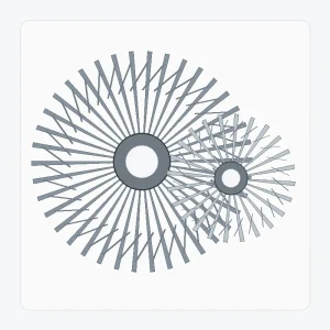
En specialbyggd spiralformad konisk kugghjulssats är uppbyggd kring projektspecifik geometri snarare än en offentlig lagertabell. Den användbara definitionen inkluderar båda medlemmarna i paret, axelförhållandet, kuggdata, monteringsdatum, gränssnitt och de tillverknings-/inspektionskrav som faktiskt kontrolleras.
Bästa utgångspunkt: En ny eller kontrollerad konstruktion där både element, axelarrangemang och acceptanskriterier kan definieras på ritningar.
Vad den här produktfamiljen är utformad för att lösa
Denna konfiguration är den bredaste utgångspunkten när ritningen äger geometrin. Den kan stödja ovanliga förhållanden, gränssnitt eller paketering, men varje extra frihetsgrad gör ritningskontrollen viktigare.
Välj den här sidan när geometrin är unik eller ännu inte knuten till ett äldre prov. Om tandfinishen är specifikt slipad ger sidan Slipad spiralformad konisk kugghjulssats en mer fokuserad processdiskussion.
Specifikation och offertförfrågan-tabell
För specialbyggda spiralformade koniska kugghjul bekräftas exakta numeriska värden för den beställda konfigurationen. Tabellen nedan identifierar de ritnings- och förfrågningsfält som behöver explicit kontroll.
| Valobjekt | Konfiguration | Anbudsförfrågan |
|---|---|---|
| Paridentitet | Matchande spiralformade koniska kugghjulspar eller projektspecifik enkomponent | Bekräfta parningsmedlemmen och drivsläktskapet. |
| Axelvinkel | Projektspecifik | Visa axelförhållandet eller monteringsritningen. |
| Förhållande / tandantal | Till ritning eller offertförfrågan | Ange båda tandantalet när det är känt. |
| Modul / diametral delning | Till ritning eller offertförfrågan | Uppskatta inte enbart utifrån ytterdiametern. |
| Tryckvinkel | Bekräfta för beställd konfiguration | Använd ritningen eller tillförlitliga äldre data för utbytesarbete. |
| Spiralvinkel och hand | Bekräfta för beställd konfiguration | Identifiera höger/vänster hand med en definierad synvinkel. |
| Monteringsavstånd / glapp | Projektspecifik | Ange bostadsdata och målintervall när det är kontrollerat. |
| Gränssnitt mellan borrning/spline/axel | Till ritning eller prov | Inkludera kilspår, splinesstandard, journaler och krav på datumpunkt. |
| Material-/värmebehandling | Till ritning eller projektgranskning | Ange obligatoriska krav på kvalitet, hårdhet eller ytskikt om dessa kontrolleras. |
| Tandfinish / kvalitet | Till ritning eller projektgranskning | Ange krav för skärning/markering och acceptansstandard eller inspektionskriterier. |
Definiera paret som ett system
Tillverkningsvägen väljs från ritningen. Ämnes- och referensbearbetning ska skapa stabila referenser för kuggskärning och senare finbearbetning. Värmebehandling och tandfinbearbetning planeras sedan så att den slutliga inspektionen använder samma kontrollerade referenspunkter.
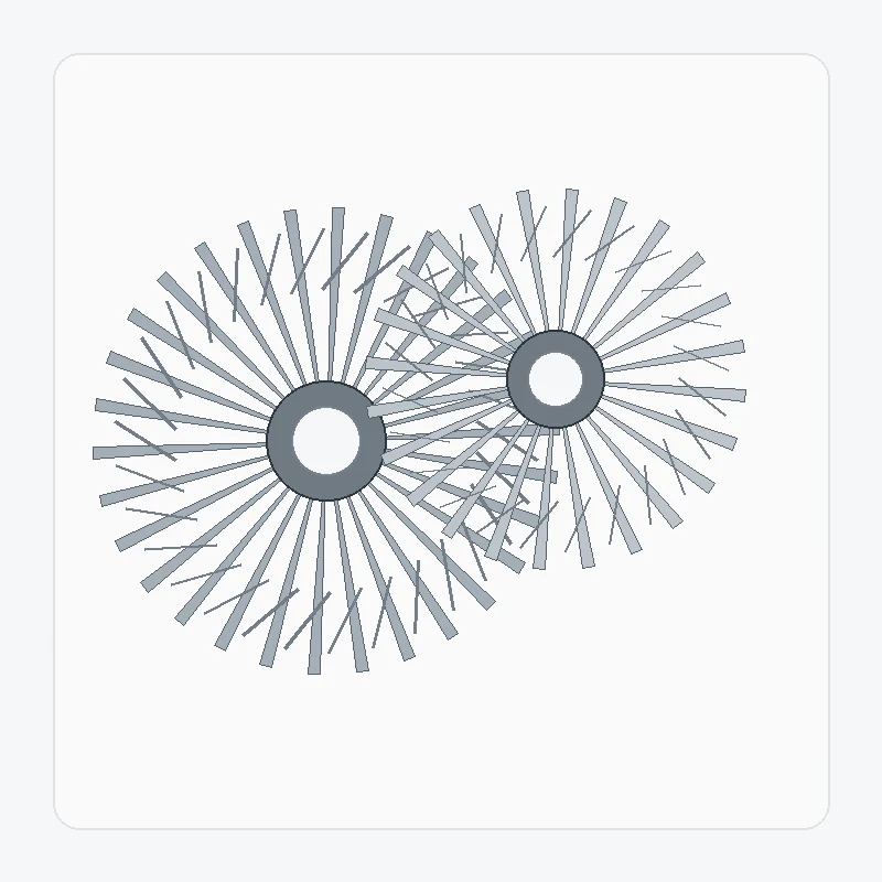
Den tekniska visualiseringen för en specialbyggd spiralformad konisk kugghjulssats är ett diskussionshjälpmedel för komponentrelationer. Den kontrollerade produktionsritningen och den godkända offerten förblir dimensionsdefinitionen för beställningen.
Gränssnitt och monteringskontroller

Parningsmedlem
Bekräfta vilket kugghjul som passar till komponenten och om båda delarna ingår i leveransen.

Datum och montering
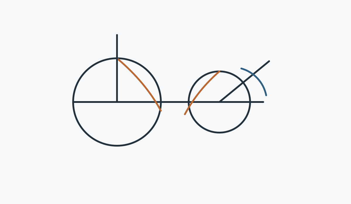
Visa ytorna och axlarna som styr monteringsavstånd, axelposition och glapp.

Materialväg
Ange kontrollerade krav för material/värmebehandling och identifiera funktioner som behöver sekundär bearbetning.

Godtagande
Lista de dimensions-, tandkvalitets-, rundgångs- eller kontaktkontroller som krävs för frigivning.
Typisk applikationspassform
Nya maskiner, kompakta rätvinkelväxlar, specialväxellådor, automationsmekanismer och alla sammansättningar där en kontrollerad ritning definierar det matchande paret.
Ansökningsblankett ska skickas med ritningen när den kan ändra materialväg, tandfinish, stödförutsättningar eller inspektionskrav.
CNC-maskiner

Vinkelstyrda drivningar och positioneringsmekanismer där monteringsstyvhet och glapp är viktiga.
Ansökningsvägledning →
Robotik och automation

Kompakta mekanismer med skärande axlar med krav på reversering och repeterbarhet.
Ansökningsvägledning →
Laserskärning och portalsystem

Riktningsändrande transmission runt portaler och automatiserad positioneringsutrustning.
Ansökningsvägledning →
Tunga lyft och lyftanordningar

Kraftiga mekanismer där stötdämpning, start/stopp och stödanordning behöver ses över.
Ansökningsvägledning →
Precisionsmaskiner

Kompakta precisionssystem med kontrollerade referenspunkter, rundgång och kontaktkrav.
Ansökningsvägledning →
Industriella växellådor

Växellådans steg som leder vridmoment genom korsande axelarrangemang.
Ansökningsvägledning →Tillverknings- och inspektionssekvens
Recension
Bekräfta ritningsrevision, paridentitet, öppna frågor och acceptanskritiska funktioner.
Planera
Definiera ämne, datumbearbetning, kugghjulsbearbetning, värmebehandling och finbearbetningssekvens.
Avsluta
Komplett tand- och gränssnittsbehandling enligt beställd rutin.
Inspektera
Kontrollera de dimensioner och växelrelaterade kriterier som överenskommits för konfigurationen.
Vad som ska inkluderas i förfrågan
| Anbudsgrupp | Rekommenderad detalj |
|---|---|
| Teknisk definition | Nuvarande ritning, parreferens, förhållande/tandantal, förhållande mellan visare och axel |
| Montering | Borrning/axel/spline, lager, husutgångspunkter, monteringsavstånd och glapp om kontrollerat |
| Tull | Hastighet, vridmoment-/belastningsspektrum, reverseringar, stötar, miljö och smörjning |
| Kvalitet | Material, värmebehandling, tandfinish, toleranser och inspektionsregister |
| Kommersiell | Prototyp och upprepningskvantitet, destination, tidpunkt och önskad handelsvillkor |
Vanliga frågor
Kan jag bara beställa en medlem av paret?
För specialbyggda spiralformade koniska kugghjul kan leverans av en del granskas när kopplingen är helt definierad. Om den befintliga kopplingen är okänd, skicka dess ritning, mått eller fysiska kugghjul innan en enskild komponent släpps.
Kan ett slitet prov kopieras direkt?
Ett prov av ett slitet specialbyggt spiralformat koniskt kugghjul kan stödja identifiering, men slitage bör inte behandlas som originalgeometri. Äldre ritningar, en oanvänd anslutningsdel och monteringsmått ger en starkare rekonstruktionsgrund.
Behöver jag välja material och värmebehandling innan offerten?
När den specialdesignade spiralformade koniska kugghjulsuppsättningen styr material- eller värmebehandling, ange det exakta kravet. Om dessa artiklar är öppna, beskriv arbetsuppgifterna och markera dem för urvalsgranskning istället för att låna en sort från en annan växel.
Hur hanteras små provmängder?
Små prover av specialbyggda spiralformade koniska kugghjul kan granskas för lämpliga nya projekt. Separera prototypkvantiteten från förväntad upprepad efterfrågan så att uppställning, inspektion och senare produktion planeras mot rätt volym.
Kommersiell planering för din offertförfrågan
För offertförfrågningar är MOQ flexibel och beror på produktform, bearbetningsväg och totalt ordervärde. Lämpliga nya projekt kan granskas för 1–5 provstycken till provpris. Olika modeller kan kombineras när ordersumman uppgår till cirka 1 500 USD. Beställningar på 1–2 stycken kan också övervägas, vanligtvis till en högre enhetskostnad eftersom uppställning och inspektion är utspridda över en mycket liten kvantitet.
För leveransplanering med offertförfrågan är typiska fönster 10–25 arbetsdagar för standarddelar, 20–45 arbetsdagar för kundanpassade komponenter och 45–120 arbetsdagar för projektliknande utrustning eller monteringar. EXW, FOB, CIF och DAP stöds vanligtvis; FCA, CFR, CPT, CIP och DDP kan diskuteras för den specifika leveransen och destinationen.
Skicka kugghjulsparet, ritning och uppgift i en offertförfrågan.
Ju tydligare parningsförhållandet och monteringsdatumen definieras, desto snabbare kan konfigurationen granskas.
Beställnings- och leveransvägledning
MOQ är flexibel beroende på produkttyp, tillverkningsväg och totalt ordervärde. Lämpliga nya projekt kan begära 1–5 provstycken till provpris. Blandade modeller kan kombineras när ordersumman uppgår till cirka 1 500 USD. Beställningar på 1–2 stycken kan granskas, även om enhetskostnaden normalt är högre.
Typiska planeringsfönster är 10–25 arbetsdagar för standarddelar, 20–45 arbetsdagar för kundanpassade komponenter och 45–120 arbetsdagar för projektliknande utrustning eller monteringar. EXW, FOB, CIF och DAP stöds vanligtvis; FCA, CFR, CPT, CIP och DDP kan diskuteras för leveransen.