Beschreibung
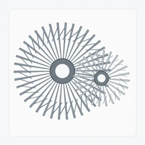
Ein kundenspezifischer Spiralkegelradsatz wird anhand projektspezifischer Geometrie und nicht anhand einer Standardtabelle gefertigt. Die sinnvolle Definition umfasst beide Zahnräder des Paares, die Achsenbeziehung, Zahndaten, Montagebezugspunkte, Schnittstellen sowie die tatsächlich zu kontrollierenden Fertigungs- und Prüfanforderungen.
Bester Ausgangspunkt: Eine neue oder kontrollierte Konstruktion, bei der sowohl die Bauteile als auch die Wellenanordnung und die Abnahmekriterien in Zeichnungen definiert werden können.
Wozu wurde diese Produktfamilie entwickelt?
Diese Konfiguration stellt den breitesten Ausgangspunkt dar, wenn die Zeichnung die Geometrie bestimmt. Sie unterstützt ungewöhnliche Seitenverhältnisse, Schnittstellen oder Anordnungen, doch jeder zusätzliche Freiheitsgrad macht die Kontrolle über die Zeichnung umso wichtiger.
Wählen Sie diese Seite, wenn die Geometrie einzigartig ist oder noch keinem bestehenden Muster zugeordnet ist. Falls die Zahnoberfläche speziell geschliffen wird, bietet die Seite „Geschliffener Spiralkegelradsatz“ eine detailliertere Prozessbeschreibung.

Spezifikations- und Angebotsanfragetabelle
Bei kundenspezifischen Spiral-Kegelradsätzen werden die genauen numerischen Werte für die bestellte Konfiguration bestätigt. Die folgende Tabelle zeigt die Zeichnungs- und Anfragefelder, die explizit geprüft werden müssen.
| Auswahlartikel | Konfiguration | RFQ-Notiz |
|---|---|---|
| Paaridentität | Passendes Spiralkegelradpaar oder projektspezifisches Einzelbauteil | Bestätigen Sie die Paarungs- und Fahrbeziehung. |
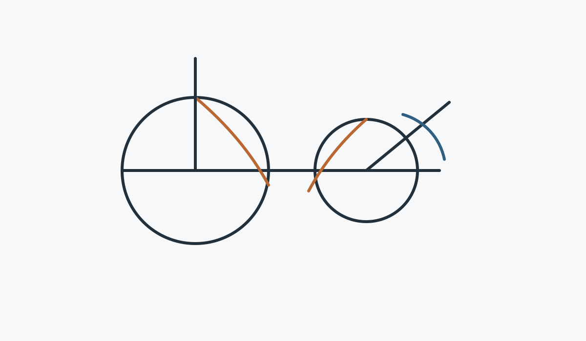
| Wellenwinkel | Projektspezifisch | Zeigen Sie die Achsenbeziehung oder die Montagezeichnung. |
| Verhältnis / Anzahl der Zähne | Zur Zeichnung oder Angebotsanfrage | Geben Sie, sofern bekannt, beide Zahnzahlen an. |
| Modul / diametrale Steigung | Zur Zeichnung oder Angebotsanfrage | Schätzen Sie nicht allein anhand des Außendurchmessers. |
| Druckwinkel | Bestätigung der bestellten Konfiguration | Verwenden Sie für die Austauscharbeiten die Zeichnung oder verlässliche Altdaten. |
| Spiralwinkel und Hand | Bestätigung der bestellten Konfiguration | Identifizieren Sie die rechte/linke Hand anhand einer festgelegten Betrachtungskonvention. |
| Montageabstand / Spiel | Projektspezifisch | Geben Sie bei kontrollierter Steuerung die Bezugspunkte für das Gehäuse und die Zielentfernung an. |
| Bohrungs-/Keilwellen-/Wellenschnittstelle | Zur Zeichnung oder zum Muster | Berücksichtigen Sie die Anforderungen an Keilnut, Keilwellenstandard, Zapfen und Bezugspunkte. |
| Material / Wärmebehandlung | Zur Zeichnungs- oder Projektprüfung | Geben Sie gegebenenfalls die vorgeschriebenen Anforderungen an Güteklasse, Härte oder Gehäuse an. |
| Zahnfinish / Qualität | Zur Zeichnungs- oder Projektprüfung | Staatliche Schnitt-/Bodenanforderungen und Abnahmestandards bzw. Inspektionskriterien. |
Das Paar wird als ein System definiert.
Der Fertigungsweg wird anhand der Zeichnung ausgewählt. Die Bearbeitung des Rohlings und der Bezugspunkte dient der Schaffung stabiler Referenzpunkte für die Zahnradfertigung und die anschließende Endbearbeitung. Wärmebehandlung und Zahnfeiltbearbeitung werden so geplant, dass die Endprüfung anhand derselben kontrollierten Bezugspunkte erfolgt.
Die technische Darstellung des kundenspezifischen Spiralkegelradsatzes dient als Diskussionsgrundlage für die Bauteilbeziehungen. Die Fertigungszeichnung und das genehmigte Angebot bleiben die Maßdefinition für die Bestellung.
Schnittstellen- und Montageprüfungen

Paarungspartner
Prüfen Sie, welches Zahnrad zu dem Bauteil passt und ob beide Teile im Lieferumfang enthalten sind.

Bezugspunkte & Montage
Zeigen Sie die Flächen und Achsen, die den Montageabstand, die Wellenposition und das Zahnflankenspiel bestimmen.

Materialweg
Staatlich geregelte Material-/Wärmebehandlungsanforderungen und Identifizierung von Merkmalen, die eine Nachbearbeitung erfordern.

Annahme
Listen Sie die Maß-, Zahnqualitäts-, Rundlauf- und Kontaktprüfungen auf, die für die Freigabe erforderlich sind.
Typische Anwendungspassform
Neumaschinen, kompakte Winkelgetriebe, Spezialgetriebe, Automatisierungsmechanismen und alle Baugruppen, bei denen eine kontrollierte Zeichnung das zusammengehörige Paar definiert.
Die Antragsunterlagen sollten immer dann mit der Zeichnung eingereicht werden, wenn sich dadurch der Materialweg, die Zahnbearbeitung, die Stützannahmen oder die Prüfanforderungen ändern können.
CNC-Werkzeugmaschinen

Rechtwinklige Antriebe und Positioniermechanismen, bei denen Montagesteifigkeit und Spiel eine Rolle spielen.
Anwendungshinweise →
Robotik & Automatisierung

Kompakte, sich kreuzende Achsenmechanismen mit reversibler Funktion und Anforderungen an die Wiederholgenauigkeit.
Anwendungshinweise →
Laserschneid- und Portalsysteme

Richtungswechselübertragung um Portale und automatische Positionierungseinrichtungen.
Anwendungshinweise →
Schwerlastheben & Hebezeuge

Hochleistungsmechanismen, bei denen Stoßbelastungen, Start-/Stopp-Vorgänge und die Stützkonstruktion überprüft werden müssen.
Anwendungshinweise →
Präzisionsmaschinen

Kompakte Präzisionssysteme mit kontrollierten Bezugspunkten, Rundlauf- und Kontaktvorgaben.
Anwendungshinweise →
Industriegetriebe

Getriebestufen, die das Drehmoment über sich kreuzende Wellenanordnungen leiten.
Anwendungshinweise →Fertigungs- und Prüfablauf
Rezension
Zeichnungsrevision bestätigen, Paaridentität klären, offene Fragen klären und akzeptanzkritische Merkmale identifizieren.
Planen
Definiere die Reihenfolge von Rohling, Bezugsbearbeitung, Zahnradfertigung, Wärmebehandlung und Endbearbeitung.
Beenden
Vollständige Zahn- und Schnittstellenbearbeitung gemäß der bestellten Route.
Überprüfen
Prüfen Sie die für die Konfiguration vereinbarten Abmessungen und getriebebezogenen Kriterien.
Was in die Anfrage aufgenommen werden sollte
| RFQ-Gruppe | Empfohlene Details |
|---|---|
| Technische Definition | Aktuelle Zeichnung, Paarbezug, Übersetzungsverhältnis/Zähneanzahl, Hand- und Achsenverhältnis |
| Montage | Bohrung/Welle/Verzahnung, Lager, Gehäusebezugspunkte, Montageabstand und Zahnflankenspiel (falls kontrolliert) |
| Pflicht | Geschwindigkeit, Drehmoment-/Lastspektrum, Richtungswechsel, Stöße, Umgebungsbedingungen und Schmierung |
| Qualität | Werkstoff, Wärmebehandlung, Zahnfeinheit, Toleranzen und Prüfprotokolle |
| Kommerziell | Prototyp- und Serienmenge, Bestimmungsort, zeitlicher Zieltermin und bevorzugte Handelsbezeichnung |
Häufig gestellte Fragen
Kann ich nur einen der beiden Teile bestellen?
Bei kundenspezifischen Spiral-Kegelradsätzen kann die Lieferung eines einzelnen Bauteils geprüft werden, sobald die Passung vollständig definiert ist. Ist die bestehende Passung unbekannt, senden Sie bitte die Zeichnung, die Maße oder ein physisches Zahnradmodell, bevor Sie ein einzelnes Bauteil freigeben.
Lässt sich ein abgenutztes Muster direkt kopieren?
Ein verschlissenes, kundenspezifisch gefertigtes Spiralkegelradsatz-Muster kann bei der Identifizierung helfen, Verschleiß sollte jedoch nicht als ursprüngliche Geometrie betrachtet werden. Ältere Zeichnungen, ein unbenutztes Gegenstück und Baugruppenmaße bieten eine solidere Grundlage für die Rekonstruktion.
Muss ich Material und Wärmebehandlung vor der Angebotsanfrage auswählen?
Wenn die Konstruktion des kundenspezifischen Spiralkegelradsatzes das Material oder die Wärmebehandlung bestimmt, geben Sie die genauen Anforderungen an. Sind diese Punkte nicht eindeutig, beschreiben Sie die Funktion und kennzeichnen Sie die Zahnräder zur Auswahlprüfung, anstatt eine Güteklasse von einem anderen Zahnrad zu übernehmen.
Wie werden kleine Probenmengen gehandhabt?
Für geeignete neue Projekte können kleine Muster von kundenspezifischen Spiral-Kegelradsätzen geprüft werden. Die Prototypenfertigung sollte von der erwarteten Serienproduktion getrennt werden, damit Rüstzeiten, Prüfungen und die spätere Produktion entsprechend dem korrekten Volumen geplant werden können.
Kommerzielle Planung für Ihre Angebotsanfrage
Für die Angebotsanfrage ist die Mindestbestellmenge flexibel und hängt von der Produktform, dem Bearbeitungsweg und dem Gesamtbestellwert ab. Geeignete neue Projekte können anhand von 1–5 Musterstücken zum Musterpreis geprüft werden. Verschiedene Modelle lassen sich kombinieren, sobald der Gesamtbestellwert ca. 1.500 USD erreicht. Bestellungen von 1–2 Stück sind ebenfalls möglich, in der Regel jedoch zu höheren Stückkosten, da sich Rüst- und Prüfaufwand auf eine sehr geringe Menge verteilen.
Für die Angebotsanfrage und Lieferplanung gelten üblicherweise folgende Lieferzeiträume: 10–25 Werktage für Standardteile, 20–45 Werktage für kundenspezifische Komponenten und 45–120 Werktage für projektbezogene Anlagen oder Baugruppen. Gängige Lieferbedingungen sind EXW, FOB, CIF und DAP; FCA, CFR, CPT, CIP und DDP können individuell für die jeweilige Lieferung und den Bestimmungsort vereinbart werden.
Senden Sie das Zahnradpaar, die Zeichnung und die Betriebsart in einer einzigen Angebotsanfrage.
Je klarer die Passungsbeziehung und die Montagebezugspunkte definiert sind, desto schneller kann die Konfiguration überprüft werden.
Bestell- und Lieferhinweise
Die Mindestbestellmenge (MOQ) ist je nach Produkttyp, Fertigungsweg und Gesamtbestellwert flexibel. Geeignete neue Projekte können 1–5 Musterstücke zum Musterpreis anfordern. Verschiedene Modelle können kombiniert werden, wenn der Gesamtbestellwert ca. 1.500 USD erreicht. Bestellungen von 1–2 Stück können geprüft werden, wobei die Stückkosten in der Regel höher sind.
Die üblichen Planungszeiträume betragen 10–25 Werktage für Standardteile, 20–45 Werktage für kundenspezifische Komponenten und 45–120 Werktage für projektbezogene Anlagen oder Baugruppen. EXW, FOB, CIF und DAP werden üblicherweise unterstützt; FCA, CFR, CPT, CIP und DDP können für den Versand individuell vereinbart werden.