Description
A custom spiral bevel gear set is built around project-specific geometry rather than a public stock table. The useful definition includes both members of the pair, the axis relationship, tooth data, mounting datums, interfaces and the manufacturing/inspection requirements that are actually controlled.
Best starting point: A new or controlled design where both members, the shaft arrangement and the acceptance criteria can be defined on drawings.
What this product family is designed to solve
This configuration is the broadest starting point when the drawing owns the geometry. It can support unusual ratios, interfaces or packaging, but every extra degree of freedom makes drawing control more important.
Choose this page when geometry is unique or not yet tied to a legacy sample. If the tooth finish is specifically ground, the Ground Spiral Bevel Gear Set page gives a more focused process discussion.
Specification and RFQ table
For custom spiral bevel gear set, exact numerical values are confirmed for the ordered configuration. The table below identifies the drawing and enquiry fields that need explicit control.
| Selection item | Configuration | RFQ note |
|---|---|---|
| Pair identity | Matched spiral bevel gear pair or project-specific single component | Confirm the mating member and driving relationship. |
| Shaft angle | Project-specific | Show the axis relationship or assembly drawing. |
| Ratio / tooth counts | To drawing or RFQ | Provide both tooth counts when known. |
| Module / diametral pitch | To drawing or RFQ | Do not estimate from outside diameter alone. |
| Pressure angle | Confirm for ordered configuration | Use the drawing or reliable legacy data for replacement work. |
| Spiral angle & hand | Confirm for ordered configuration | Identify right/left hand with a defined viewing convention. |
| Mounting distance / backlash | Project-specific | Provide housing datums and target range when controlled. |
| Bore / spline / shaft interface | To drawing or sample | Include keyway, spline standard, journals and datum requirements. |
| Material / heat treatment | To drawing or project review | State mandatory grade, hardness or case requirements if controlled. |
| Tooth finish / quality | To drawing or project review | State cut/ground requirement and the acceptance standard or inspection criteria. |
Define the pair as one system
The manufacturing route is selected from the drawing. Blank and datum machining should create stable references for gear cutting and later finishing. Heat treatment and tooth finishing are then planned so the final inspection uses the same controlled datums.
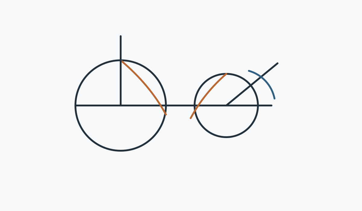
The technical visual for custom spiral bevel gear set is a discussion aid for component relationships. The controlled production drawing and approved quotation remain the dimensional definition for the order.
Interfaces and assembly checks

Mating member
Confirm which gear mates with the component and whether both members are included in the supply.

Datums & mounting
Show the surfaces and axes that control mounting distance, shaft position and backlash.

Material route
State controlled material/heat-treatment requirements and identify features that need secondary machining.

Acceptance
List the dimensional, tooth-quality, runout or contact checks that are required for release.
Typical application fit
New machinery, compact right-angle drives, special gearboxes, automation mechanisms and any assembly where a controlled drawing defines the matched pair.
Application duty should be sent with the drawing whenever it can change the material route, tooth finishing, support assumptions or inspection requirement.
CNC Machine Tools

Right-angle drives and positioning mechanisms where mounting stiffness and backlash matter.
Application guidance →
Robotics & Automation

Compact intersecting-axis mechanisms with reversing duty and repeatability requirements.
Application guidance →
Laser Cutting & Gantry Systems

Direction-changing transmission around gantries and automated positioning equipment.
Application guidance →
Heavy Lifting & Hoists

Heavy-duty mechanisms where shock, starts/stops and support arrangement need review.
Application guidance →
Precision Machinery

Compact precision systems with controlled datums, runout and contact requirements.
Application guidance →
Industrial Gearboxes

Gearbox stages that route torque through intersecting shaft arrangements.
Application guidance →Manufacturing and inspection sequence
Review
Confirm drawing revision, pair identity, open questions and acceptance-critical features.
Plan
Define blank, datum machining, gear cutting, heat treatment and finish sequence.
Finish
Complete tooth and interface finishing according to the ordered route.
Inspect
Check the dimensions and gear-related criteria agreed for the configuration.
What to include in the enquiry
| RFQ group | Recommended detail |
|---|---|
| Technical definition | Current drawing, pair reference, ratio/tooth counts, hand and axis relationship |
| Assembly | Bore/shaft/spline, bearings, housing datums, mounting distance and backlash if controlled |
| Duty | Speed, torque/load spectrum, reversals, shock, environment and lubrication |
| Quality | Material, heat treatment, tooth finish, tolerances and inspection records |
| Commercial | Prototype and repeat quantity, destination, timing target and preferred trade term |
Frequently asked questions
Can I order only one member of the pair?
For custom spiral bevel gear set, supplying one member can be reviewed when the mate is fully defined. If the existing mate is unknown, send its drawing, measurements or physical gear before releasing a single component.
Can a worn sample be copied directly?
A worn custom spiral bevel gear set sample can support identification, but wear should not be treated as original geometry. Legacy drawings, an unused mating member and assembly measurements provide a stronger reconstruction basis.
Do I need to choose material and heat treatment before the RFQ?
When the custom spiral bevel gear set design controls material or heat treatment, state the exact requirement. If those items are open, describe duty and mark them for selection review rather than borrowing a grade from another gear.
How are small sample quantities handled?
Small samples of custom spiral bevel gear set can be reviewed for suitable new projects. Separate prototype quantity from expected repeat demand so setup, inspection and later production are planned against the correct volume.
Commercial planning for your RFQ
For request a quote planning, MOQ is flexible and depends on product form, processing route and overall order value. Suitable new projects may be reviewed for 1–5 sample pieces at sample pricing. Different models can be combined when the order total reaches about USD 1,500. Orders of 1–2 pieces can also be considered, usually at a higher unit cost because setup and inspection are spread across a very small quantity.
For request a quote delivery planning, typical windows are 10–25 working days for standard parts, 20–45 working days for customized components and 45–120 working days for project-type equipment or assemblies. EXW, FOB, CIF and DAP are commonly supported; FCA, CFR, CPT, CIP and DDP can be discussed for the specific shipment and destination.
Send the gear pair, drawing and duty in one RFQ.
The more clearly the mating relationship and assembly datums are defined, the faster the configuration can be reviewed.
Ordering & delivery guidance
MOQ is flexible by product type, manufacturing route and total order value. Suitable new projects may request 1–5 sample pieces at sample pricing. Mixed models can be combined when the order total reaches approximately USD 1,500. Orders of 1–2 pieces can be reviewed, although unit cost is normally higher.
Typical planning windows are 10–25 working days for standard parts, 20–45 working days for customized components and 45–120 working days for project-type equipment or assemblies. EXW, FOB, CIF and DAP are commonly supported; FCA, CFR, CPT, CIP and DDP can be discussed for the shipment.