Description
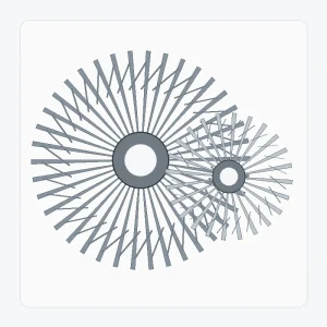
A custom spiral bevel gear set is built around project-specific geometry rather than a public stock table. The useful definition includes both members of the pair, the axis relationship, tooth data, mounting datums, interfaces and the manufacturing/inspection requirements that are actually controlled.
Best starting point: A new or controlled design where both members, the shaft arrangement and the acceptance criteria can be defined on drawings.
What this product family is designed to solve
This configuration is the broadest starting point when the drawing owns the geometry. It can support unusual ratios, interfaces or packaging, but every extra degree of freedom makes drawing control more important.
Choose this page when geometry is unique or not yet tied to a legacy sample. If the tooth finish is specifically ground, the Ground Spiral Bevel Gear Set page gives a more focused process discussion.
Specification and RFQ table
For custom spiral bevel gear set, exact numerical values are confirmed for the ordered configuration. The table below identifies the drawing and enquiry fields that need explicit control.
| Selection item | Configuration | RFQ note |
|---|---|---|
| Pair identity | Matched spiral bevel gear pair or project-specific single component | Confirm the mating member and driving relationship. |
| Shaft angle | Project-specific | Show the axis relationship or assembly drawing. |
| Ratio / tooth counts | To drawing or RFQ | Provide both tooth counts when known. |
| Module / diametral pitch | To drawing or RFQ | Do not estimate from outside diameter alone. |
| Pressure angle | Confirm for ordered configuration | Use the drawing or reliable legacy data for replacement work. |
| Spiral angle & hand | Confirm for ordered configuration | Identify right/left hand with a defined viewing convention. |
| Mounting distance / backlash | Project-specific | Provide housing datums and target range when controlled. |
| Bore / spline / shaft interface | To drawing or sample | Include keyway, spline standard, journals and datum requirements. |
| Material / heat treatment | To drawing or project review | State mandatory grade, hardness or case requirements if controlled. |
| Tooth finish / quality | To drawing or project review | State cut/ground requirement and the acceptance standard or inspection criteria. |
Define the pair as one system
The manufacturing route is selected from the drawing. Blank and datum machining should create stable references for gear cutting and later finishing. Heat treatment and tooth finishing are then planned so the final inspection uses the same controlled datums.
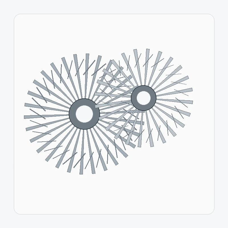
The technical visual for custom spiral bevel gear set is a discussion aid for component relationships. The controlled production drawing and approved quotation remain the dimensional definition for the order.
Interfaces and assembly checks

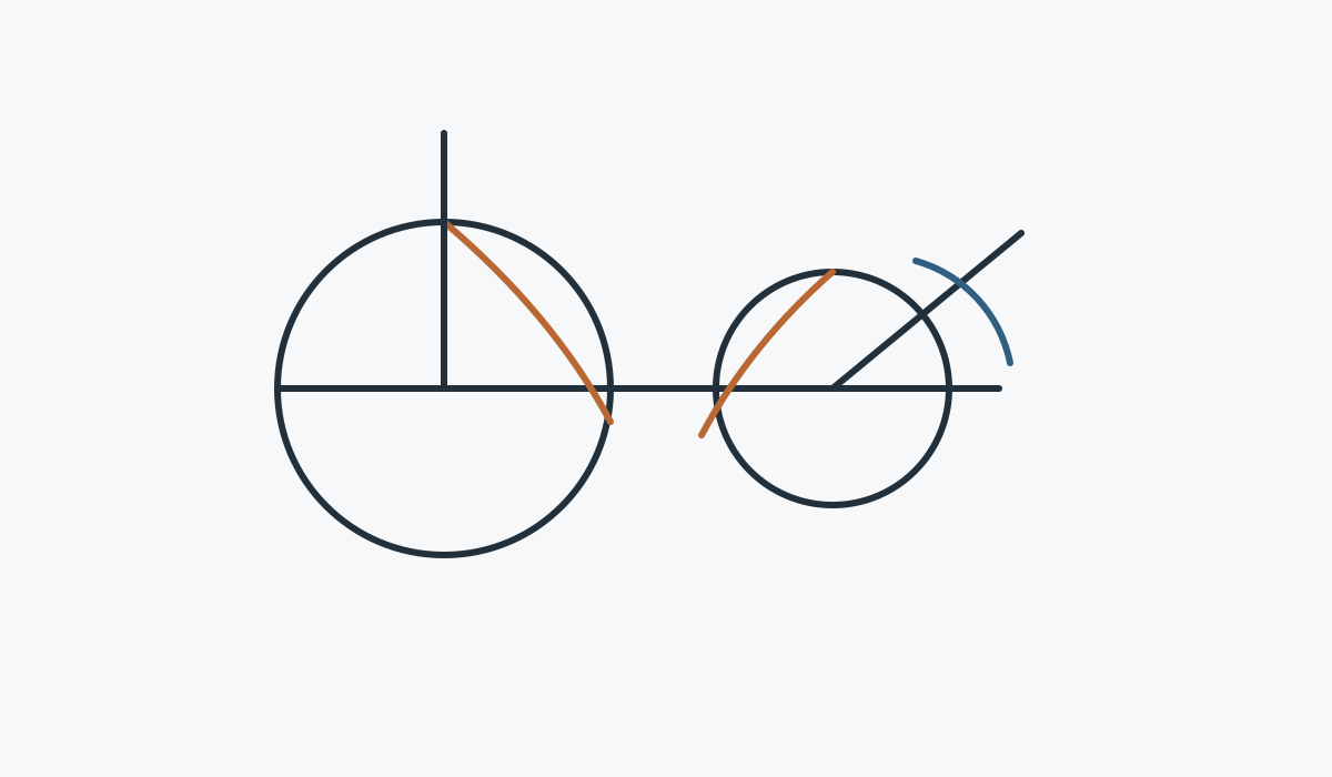
Mating member
Confirm which gear mates with the component and whether both members are included in the supply.

Datums & mounting
Show the surfaces and axes that control mounting distance, shaft position and backlash.

Material route
State controlled material/heat-treatment requirements and identify features that need secondary machining.

Acceptance
List the dimensional, tooth-quality, runout or contact checks that are required for release.
Typical application fit
New machinery, compact right-angle drives, special gearboxes, automation mechanisms and any assembly where a controlled drawing defines the matched pair.
Application duty should be sent with the drawing whenever it can change the material route, tooth finishing, support assumptions or inspection requirement.
Machines-outils à commande numérique

Entraînements à angle droit et mécanismes de positionnement où la rigidité de montage et le jeu sont importants.
Guide de candidature →
Robotique et automatisation

Mécanismes compacts à axes sécants avec fonctions réversibles et exigences de répétabilité.
Guide de candidature →
Systèmes de découpe laser et de portique

Transmission à changement de direction autour des portiques et des équipements de positionnement automatisés.
Guide de candidature →
Levage de charges lourdes et palans

Mécanismes robustes nécessitant une révision des dispositifs de choc, de démarrage/arrêt et de support.
Guide de candidature →
Machines de précision

Systèmes de précision compacts avec références, faux-rond et exigences de contact contrôlés.
Guide de candidature →
Réducteurs industriels

Étages de boîte de vitesses qui acheminent le couple à travers des agencements d'arbres entrecroisés.
Guide de candidature →Manufacturing and inspection sequence
Review
Confirm drawing revision, pair identity, open questions and acceptance-critical features.
Plan
Define blank, datum machining, gear cutting, heat treatment and finish sequence.
Finish
Complete tooth and interface finishing according to the ordered route.
Inspect
Check the dimensions and gear-related criteria agreed for the configuration.
What to include in the enquiry
| RFQ group | Recommended detail |
|---|---|
| Technical definition | Current drawing, pair reference, ratio/tooth counts, hand and axis relationship |
| Assembly | Bore/shaft/spline, bearings, housing datums, mounting distance and backlash if controlled |
| Duty | Speed, torque/load spectrum, reversals, shock, environment and lubrication |
| Quality | Material, heat treatment, tooth finish, tolerances and inspection records |
| Commercial | Prototype and repeat quantity, destination, timing target and preferred trade term |
Frequently asked questions
Can I order only one member of the pair?
For custom spiral bevel gear set, supplying one member can be reviewed when the mate is fully defined. If the existing mate is unknown, send its drawing, measurements or physical gear before releasing a single component.
Can a worn sample be copied directly?
A worn custom spiral bevel gear set sample can support identification, but wear should not be treated as original geometry. Legacy drawings, an unused mating member and assembly measurements provide a stronger reconstruction basis.
Do I need to choose material and heat treatment before the RFQ?
When the custom spiral bevel gear set design controls material or heat treatment, state the exact requirement. If those items are open, describe duty and mark them for selection review rather than borrowing a grade from another gear.
How are small sample quantities handled?
Small samples of custom spiral bevel gear set can be reviewed for suitable new projects. Separate prototype quantity from expected repeat demand so setup, inspection and later production are planned against the correct volume.
Planification commerciale pour votre demande de devis
Pour toute demande de devis, la quantité minimale de commande (MOQ) est flexible et dépend du type de produit, du procédé de fabrication et du montant total de la commande. Les nouveaux projets peuvent être étudiés pour 1 à 5 échantillons à un prix préférentiel. Différents modèles peuvent être combinés lorsque le total de la commande atteint environ 1 500 USD. Les commandes de 1 à 2 pièces sont également envisageables, généralement à un coût unitaire plus élevé, car les frais de mise en place et de contrôle sont concentrés sur une très petite quantité.
Pour toute demande de devis, les délais de livraison sont généralement de 10 à 25 jours ouvrés pour les pièces standard, de 20 à 45 jours ouvrés pour les composants sur mesure et de 45 à 120 jours ouvrés pour les équipements ou assemblages spécifiques à un projet. Les incoterms EXW, FOB, CIF et DAP sont couramment proposés ; les incoterms FCA, CFR, CPT, CIP et DDP peuvent être discutés en fonction de l’expédition et de la destination.
Veuillez inclure la paire d'engrenages, le schéma et le descriptif du service dans une seule demande de devis.
Plus les relations d'accouplement et les données d'assemblage sont définies clairement, plus la configuration peut être examinée rapidement.
Conseils pour les commandes et la livraison
La quantité minimale de commande (MOQ) est flexible et dépend du type de produit, du procédé de fabrication et du montant total de la commande. Pour les nouveaux projets, il est possible de commander de 1 à 5 échantillons à un tarif préférentiel. Différents modèles peuvent être combinés lorsque le montant total de la commande atteint environ 1 500 USD. Les commandes de 1 à 2 pièces peuvent être étudiées, bien que le coût unitaire soit généralement plus élevé.
Les délais de planification habituels sont de 10 à 25 jours ouvrables pour les pièces standard, de 20 à 45 jours ouvrables pour les composants sur mesure et de 45 à 120 jours ouvrables pour les équipements ou assemblages spécifiques à un projet. Les incoterms EXW, FOB, CIF et DAP sont couramment pris en charge ; les incoterms FCA, CFR, CPT, CIP et DDP peuvent être envisagés pour l’expédition.