Beschrijving
Het vervangen van een spiraalvormig kegeltandwiel begint met het scheiden van de oorspronkelijke ontwerpgegevens van de slijtage. Een beschadigde tand, een vervormde boring of een verschoven contactpatroon kunnen de oorzaak van het defect aangeven, maar dit betekent niet automatisch dat de oorspronkelijke geometrie klopt. De afmetingen van het tandwiel en de behuizing zijn vaak essentieel.
Beste uitgangspunt: Een versleten, verouderd of ongedocumenteerd paar waarvan de originele fabricagegegevens onvolledig zijn en de assemblage zorgvuldig gereconstrueerd moet worden.
Wat deze productfamilie moet oplossen
Het doel is niet om een versleten vorm te kopiëren. Het is om het paar, de interfaces en de montageverhouding voldoende nauwkeurig te identificeren om een nieuwe, gecontroleerde configuratie te kunnen definiëren. Oude tekeningen, ongebruikte exemplaren, onderdeelnummers en inspectieverslagen kunnen hierbij van pas komen, mits hun relevantie duidelijk is.
Gebruik deze pagina voor onderhoud en werkzaamheden aan verouderde onderdelen. Als er al een complete, gecontroleerde tekening bestaat en er geen omgekeerde identificatie nodig is, is de productfamilie voor maatwerk of standaardonderdelen wellicht een directere route.
Specificatie- en offerteaanvraagtabel
Voor een vervangende spiraalvormige kegeltandwielset worden de exacte numerieke waarden voor de bestelde configuratie bevestigd. De onderstaande tabel geeft aan op welke tekening- en aanvraagvelden expliciete controle vereist is.
| Selectie-item | Configuratie | Offerteaanvraag |
|---|---|---|
| Paar identiteit | Een passend paar spiraalvormige kegeltandwielen of een projectspecifiek los onderdeel. | Bevestig de relatie tussen het paringslid en de bestuurder. |
| Schachthoek | Projectspecifiek | Toon de asrelatie of de samenstellingstekening. |
| Verhouding / aantal tanden | Naar tekening of offerteaanvraag | Geef beide aantallen tanden op indien bekend. |
| Module / diametrale spoed | Naar tekening of offerteaanvraag | Schat de diameter niet alleen op basis van de buitendiameter. |
| Drukhoek | Bevestig de bestelde configuratie | Gebruik de tekening of betrouwbare, bestaande gegevens voor vervangingswerkzaamheden. |
| Spiraalhoek en hand | Bevestig de bestelde configuratie | Identificeer de linker- en rechterhand aan de hand van een vastgestelde kijkconventie. |
| Montageafstand / speling | Projectspecifiek | Geef de referentiepunten voor de behuizing en het doelbereik op wanneer dit gecontroleerd wordt. |
| Boring / spiebaan / as-interface | Naar tekening of voorbeeld | Vermeld de spiebaan, de spiebaanstandaard, de lagertappen en de referentiepunten. |
| Materiaal / warmtebehandeling | Voor een tekening of projectbeoordeling | Indien van toepassing, dient u de verplichte kwaliteits-, hardheids- of behuizingseisen te vermelden. |
| Tandafwerking / kwaliteit | Voor een tekening of projectbeoordeling | De staat stelt eisen aan de zaagsneden/grondbewerking en hanteert de acceptatienorm of inspectiecriteria. |
Meet het onderdeel en de complete assemblage op voordat u deze demonteert.
De eerste fase is de identificatie: beide onderdelen, het aantal tanden, de hand, de zichtbare geometrie, referentiepunten van de as/behuizing en de staat van het monster. Zodra de beoogde geometrie is vastgesteld, kan het project overgaan naar materiaal-/procesplanning en de definitieve goedkeuring van de tekening vóór de productie.
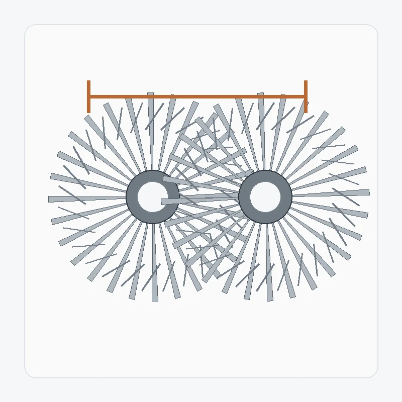
De technische afbeelding voor de vervangende spiraalvormige kegeltandwielset dient als hulpmiddel bij de bespreking van de onderlinge verhoudingen van de componenten. De gecontroleerde productietekening en de goedgekeurde offerte blijven de maatspecificaties voor de bestelling.
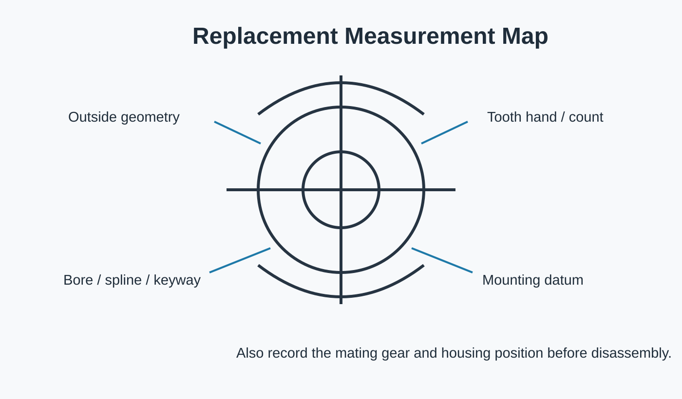
Interfaces en assemblagecontroles

paringslid
Controleer welk tandwiel bij het onderdeel hoort en of beide onderdelen bij de levering zijn inbegrepen.

Referentiepunten en montage
Toon de oppervlakken en assen die de montageafstand, de aspositie en de speling bepalen.

Materiaalroute
De staat stelt eisen aan materiaal/warmtebehandeling vast en identificeert kenmerken die nabewerking vereisen.

Aanvaarding
Geef een lijst van de dimensionale, tandkwaliteits-, rondloop- of contactcontroles die vereist zijn voor vrijgave.
Typische toepassingspasvorm
Bestaande industriële tandwielkasten, werktuigmachines, automatiseringsapparatuur, hijsmechanismen en andere machines waar het originele paar in een bestaande behuizing en asconfiguratie moet passen.
De aanvraag moet samen met de tekening worden verzonden wanneer deze wijzigingen kan aanbrengen in de materiaaltoevoer, de afwerking van de tanden, de aannames met betrekking tot de ondersteuning of de inspectie-eisen.
CNC-bewerkingsgereedschap

Haakse aandrijvingen en positioneringsmechanismen waarbij montagestijfheid en speling van belang zijn.
Aanvraagrichtlijnen →
Robotica en automatisering

Compacte mechanismen met kruisende assen die omkeerbaar zijn en aan herhaalbaarheidseisen voldoen.
Aanvraagrichtlijnen →
Lasersnij- en portaalsystemen

Richtingsveranderende transmissie rondom portaalkranen en geautomatiseerde positioneringsapparatuur.
Aanvraagrichtlijnen →
Zwaar tillen en hijsen

Zware mechanismen waarbij schokdemping, start-/stopmechanismen en ondersteuningsconstructies moeten worden herzien.
Aanvraagrichtlijnen →
Precisiemachines

Compacte precisiesystemen met gecontroleerde referentiepunten, slingering en contactvereisten.
Aanvraagrichtlijnen →
Industriële tandwielkasten

Versnellingsbaktrappen die koppel overbrengen via kruisende asconstructies.
Aanvraagrichtlijnen →Productie- en inspectievolgorde
Beoordeling
Bevestig de herziening van de tekening, de identiteit van het paar, de open vragen en de acceptatiekritische kenmerken.
Plan
Definieer de volgorde van bewerking (blank), referentiebewerking, tandwielsnijden, warmtebehandeling en afwerking.
Finish
Voltooi de afwerking van de tanden en de interface volgens de bestelde route.
Inspecteren
Controleer de afmetingen en de overeengekomen criteria met betrekking tot de tandwielen voor de configuratie.
Wat moet er in de aanvraag worden opgenomen?
| RFQ-groep | Aanbevolen detail |
|---|---|
| Technische definitie | Huidige tekening, referentiepaar, verhouding/aantal tanden, relatie tussen hand en as |
| Montage | Boring/as/vertanding, lagers, referentiepunten van de behuizing, montageafstand en speling indien gecontroleerd |
| Plicht | Snelheid, koppel/belastingsspectrum, omkeringen, schokken, omgeving en smering |
| Kwaliteit | Materiaal, warmtebehandeling, tandafwerking, toleranties en inspectiegegevens |
| Commercieel | Prototype- en herhaalhoeveelheid, bestemming, streeftijd en gewenste handelsvoorwaarden. |
Veelgestelde vragen
Kan ik slechts één van de twee bestellen?
Voor een vervangende set spiraalvormige kegeltandwielen kan de levering van één onderdeel worden beoordeeld zodra de bijbehorende koppeling volledig is vastgesteld. Als de bestaande koppeling onbekend is, stuur dan de tekening, afmetingen of het fysieke tandwiel op voordat u een enkel onderdeel vrijgeeft.
Kan een versleten exemplaar direct worden gekopieerd?
Een versleten vervangend spiraalvormig kegeltandwielset kan helpen bij de identificatie, maar slijtage mag niet als originele geometrie worden beschouwd. Oude tekeningen, een ongebruikt tegenstuk en montagemetingen bieden een sterkere basis voor de reconstructie.
Moet ik het materiaal en de warmtebehandeling kiezen voordat ik de offerteaanvraag indien?
Als het ontwerp van de vervangende spiraalvormige kegeltandwielset eisen stelt aan het materiaal of de warmtebehandeling, geef dan de exacte vereisten aan. Als deze punten openstaan, beschrijf dan de toepassing en markeer ze voor beoordeling bij de selectie, in plaats van een kwaliteit over te nemen van een ander tandwiel.
Hoe worden kleine monsterhoeveelheden verwerkt?
Kleine aantallen vervangende spiraalvormige kegeltandwielsets kunnen worden beoordeeld voor geschikte nieuwe projecten. De prototypehoeveelheid moet worden gescheiden van de verwachte herhaalvraag, zodat de insteltijd, inspectie en latere productie kunnen worden gepland op basis van het juiste volume.
Commerciële planning voor uw offerteaanvraag
Voor het aanvragen van een offerte is de minimale bestelhoeveelheid (MOQ) flexibel en afhankelijk van de productvorm, de productieroute en de totale orderwaarde. Geschikte nieuwe projecten kunnen worden beoordeeld aan de hand van 1 tot 5 proefexemplaren tegen een proefprijs. Verschillende modellen kunnen worden gecombineerd wanneer de totale orderwaarde ongeveer USD 1.500 bedraagt. Bestellingen van 1 tot 2 stuks kunnen ook worden overwogen, meestal tegen een hogere kostprijs per stuk omdat de instel- en inspectiekosten over een zeer kleine hoeveelheid worden verdeeld.
Voor een offerteaanvraag en levertijdplanning zijn de gebruikelijke levertijden 10-25 werkdagen voor standaardonderdelen, 20-45 werkdagen voor maatwerkcomponenten en 45-120 werkdagen voor projectapparatuur of -assemblages. EXW, FOB, CIF en DAP worden veelvuldig ondersteund; FCA, CFR, CPT, CIP en DDP kunnen worden besproken afhankelijk van de specifieke zending en bestemming.
Stuur het tandwielpaar, de tekening en de specificaties in één offerteaanvraag.
Hoe duidelijker de koppelingsrelatie en de montage-referentiepunten zijn gedefinieerd, hoe sneller de configuratie kan worden gecontroleerd.
Bestel- en leveringsinstructies
De minimale bestelhoeveelheid (MOQ) is flexibel en afhankelijk van het producttype, de productiemethode en de totale orderwaarde. Voor geschikte nieuwe projecten kunnen 1 tot 5 proefexemplaren tegen proefprijs worden aangevraagd. Gemengde modellen kunnen worden gecombineerd wanneer de totale orderwaarde ongeveer USD 1.500 bedraagt. Bestellingen van 1 of 2 stuks kunnen worden beoordeeld, hoewel de kosten per stuk doorgaans hoger liggen.
De gebruikelijke levertijd bedraagt 10-25 werkdagen voor standaardonderdelen, 20-45 werkdagen voor maatwerkcomponenten en 45-120 werkdagen voor projectapparatuur of -assemblages. EXW, FOB, CIF en DAP worden veelvuldig ondersteund; FCA, CFR, CPT, CIP en DDP kunnen in overleg worden geregeld voor de verzending.

























