Descrição
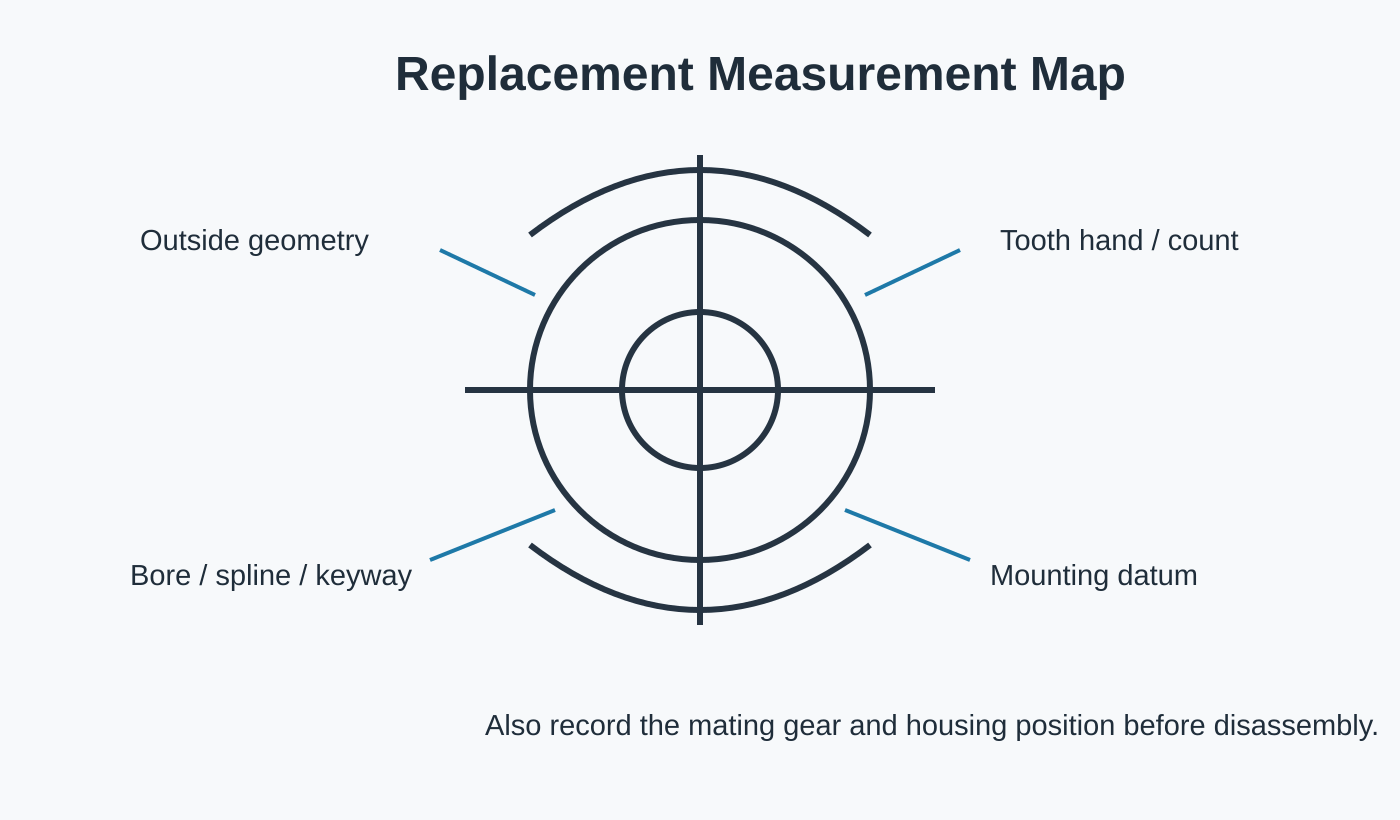
O trabalho de substituição de engrenagens cônicas espirais começa com a separação das informações do projeto original do desgaste em serviço. Um dente danificado, um furo distorcido ou um padrão de contato alterado podem descrever a falha, mas não descrevem automaticamente a geometria original. As medidas da engrenagem e da carcaça são frequentemente essenciais.
Melhor ponto de partida: Um par de relógios desgastado, obsoleto ou sem documentação, onde os dados originais de fabricação estão incompletos e a montagem precisa ser cuidadosamente reconstruída.
O que esta família de produtos resolve
O objetivo não é copiar um formato desgastado. É identificar o par, as interfaces e a relação de montagem com precisão suficiente para definir uma nova configuração controlada. Desenhos antigos, amostras não utilizadas, números de peças e registros de inspeção podem ser úteis quando sua relevância for clara.
Use esta página para manutenção e trabalhos com peças obsoletas. Se já existir um desenho controlado completo e não for necessária a identificação reversa, a família de produtos personalizada ou padrão pode ser um caminho mais direto.
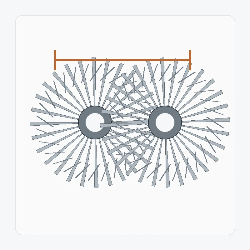
Tabela de especificações e solicitação de cotação
Para o conjunto de engrenagens cônicas helicoidais de substituição, os valores numéricos exatos são confirmados para a configuração solicitada. A tabela abaixo identifica os campos de desenho e consulta que necessitam de controle explícito.
| Item de seleção | Configuração | Nota de solicitação de cotação |
|---|---|---|
| Identidade do par | Par de engrenagens cônicas espirais combinadas ou componente único específico para o projeto. | Confirme o membro reprodutor e a relação de condução. |
| Ângulo do eixo | Específico do projeto | Mostre o diagrama de relação entre os eixos ou o desenho de montagem. |
| Proporção / número de dentes | Para desenho ou solicitação de cotação | Forneça a contagem de ambos os dentes, quando conhecida. |
| Módulo / passo diametral | Para desenho ou solicitação de cotação | Não faça estimativas baseando-se apenas no diâmetro externo. |
| Ângulo de pressão | Confirme a configuração solicitada. | Utilize o desenho ou dados legados confiáveis para o trabalho de substituição. |
| Ângulo espiral e mão | Confirme a configuração solicitada. | Identificar a mão direita/esquerda com base em uma convenção de visualização definida. |
| Distância de montagem / folga | Específico do projeto | Forneça os pontos de referência da habitação e o alcance alvo quando controlados. |
| Interface furo/estria/eixo | Para desenho ou amostra | Incluir requisitos de chaveta, padrão de estria, mancais e referência. |
| Material / tratamento térmico | Para revisão de desenho ou projeto | Indique, se houver, os requisitos obrigatórios de grau, dureza ou revestimento. |
| Acabamento/qualidade dos dentes | Para revisão de desenho ou projeto | Requisitos estaduais de corte/nivelamento e padrão de aceitação ou critérios de inspeção. |
Meça a peça e o conjunto antes de desmontá-lo.
A primeira etapa é a identificação: ambos os componentes, número de dentes, posição manual, geometria visível, referências do eixo/carcaça e condição da amostra. Uma vez definida a geometria pretendida, o projeto pode avançar para o planejamento de materiais/processos e aprovação do desenho final antes da fabricação.
A representação visual técnica do conjunto de engrenagens cônicas helicoidais de substituição serve como auxílio para a discussão das relações entre os componentes. O desenho de produção controlado e o orçamento aprovado permanecem como a definição dimensional do pedido.
Interfaces e verificações de montagem

Membro reprodutor
Confirme qual engrenagem é compatível com o componente e se ambos os itens estão incluídos no fornecimento.

Referências e montagem
Mostre as superfícies e os eixos que controlam a distância de montagem, a posição do eixo e a folga.

Rota do material
Requisitos estaduais para materiais/tratamentos térmicos e identificação de características que necessitam de usinagem secundária.

Aceitação
Liste as verificações dimensionais, de qualidade dos dentes, de excentricidade ou de contato que são necessárias para a liberação.
Ajuste típico de aplicação
Caixas de engrenagens industriais existentes, máquinas-ferramenta, equipamentos de automação, mecanismos de elevação e outras máquinas onde o par original deve se encaixar em um arranjo de carcaça e eixo já estabelecido.
A solicitação de aplicação deve ser enviada juntamente com o desenho sempre que houver alteração no processo de fabricação do material, no acabamento dos dentes, nas hipóteses de suporte ou nos requisitos de inspeção.
Máquinas-ferramenta CNC

Mecanismos de acionamento e posicionamento em ângulo reto, onde a rigidez de montagem e a folga são importantes.
Orientações para candidatura →
Robótica e Automação

Mecanismos compactos de eixos que se cruzam, com requisitos de reversão de ciclo e repetibilidade.
Orientações para candidatura →
Corte a laser e sistemas de pórtico

Transmissão com mudança de direção em torno de pórticos e equipamentos de posicionamento automatizados.
Orientações para candidatura →
Levantamento e içamento de cargas pesadas

Mecanismos de serviço pesado onde choques, partidas/paradas e arranjos de suporte precisam ser revistos.
Orientações para candidatura →
Maquinaria de Precisão

Sistemas compactos de precisão com referências controladas, requisitos de concentricidade e contato.
Orientações para candidatura →
Caixas de Engrenagens Industriais

Estágios de caixa de engrenagens que transmitem o torque através de conjuntos de eixos que se cruzam.
Orientações para candidatura →Sequência de fabricação e inspeção
Análise
Confirme a revisão do desenho, a identidade do par, as questões em aberto e os elementos críticos para a aceitação.
Plano
Defina a sequência de usinagem do blank, usinagem de referência, corte de engrenagens, tratamento térmico e acabamento.
Terminar
Finalização completa dos dentes e da interface de acordo com o procedimento solicitado.
Inspecionar
Verifique as dimensões e os critérios relacionados à engrenagem acordados para a configuração.
O que incluir na consulta
| Grupo RFQ | Detalhes recomendados |
|---|---|
| Definição técnica | Desenho atual, referência de pares, relação entre proporção e número de dentes, relação entre mão e eixo |
| Conjunto | Diâmetro do furo/eixo/estria, rolamentos, pontos de referência da carcaça, distância de montagem e folga, se controlada. |
| Obrigação | Velocidade, espectro de torque/carga, inversões, choque, ambiente e lubrificação. |
| Qualidade | Material, tratamento térmico, acabamento dos dentes, tolerâncias e registros de inspeção |
| Comercial | Quantidade de protótipos e repetições, destino, prazo alvo e termos comerciais preferenciais. |
Perguntas frequentes
Posso encomendar apenas um dos itens do par?
Para conjuntos de engrenagens cônicas helicoidais de substituição, o fornecimento de um único componente pode ser analisado quando a relação de acoplamento estiver totalmente definida. Caso a relação de acoplamento existente seja desconhecida, envie o desenho, as medidas ou a engrenagem física antes de liberar qualquer componente.
É possível copiar diretamente uma amostra desgastada?
Uma amostra de um conjunto de engrenagens cônicas espirais de reposição desgastadas pode auxiliar na identificação, mas o desgaste não deve ser considerado como geometria original. Desenhos antigos, um componente de acoplamento não utilizado e medidas de montagem fornecem uma base mais sólida para a reconstrução.
Preciso escolher o material e o tratamento térmico antes da solicitação de cotação?
Quando o projeto do conjunto de engrenagens cônicas helicoidais de substituição exigir restrições de material ou tratamento térmico, especifique os requisitos exatos. Se esses itens forem variáveis, descreva a aplicação e marque-os para revisão na seleção, em vez de utilizar a especificação de outra engrenagem.
Como são tratadas as pequenas quantidades de amostras?
Pequenas amostras do conjunto de engrenagens cônicas espirais de reposição podem ser analisadas para novos projetos adequados. Separe a quantidade do protótipo da demanda esperada de peças repetidas, para que a preparação, a inspeção e a produção posterior sejam planejadas com base no volume correto.
Planejamento comercial para sua solicitação de cotação.
Para o planejamento de orçamentos, a quantidade mínima de pedido (MOQ) é flexível e depende do formato do produto, do processo de fabricação e do valor total do pedido. Novos projetos adequados podem ser analisados para 1 a 5 peças de amostra, com preços especiais para amostras. Diferentes modelos podem ser combinados quando o valor total do pedido atingir aproximadamente USD 1.500. Pedidos de 1 a 2 peças também podem ser considerados, geralmente com um custo unitário mais alto, pois a preparação e a inspeção são distribuídas em uma quantidade muito pequena.
Para solicitar um orçamento e planejar a entrega, os prazos típicos são de 10 a 25 dias úteis para peças padrão, de 20 a 45 dias úteis para componentes personalizados e de 45 a 120 dias úteis para equipamentos ou conjuntos de projetos especiais. Os termos EXW, FOB, CIF e DAP são comumente aceitos; FCA, CFR, CPT, CIP e DDP podem ser discutidos para cada remessa e destino específicos.
Envie o par de engrenagens, o desenho e a especificação de funcionamento em uma única solicitação de cotação.
Quanto mais claramente definidas forem a relação de acoplamento e os dados de montagem, mais rapidamente a configuração poderá ser revisada.
Orientações sobre encomendas e entregas
A quantidade mínima de encomenda (MOQ) é flexível, variando conforme o tipo de produto, o processo de fabricação e o valor total do pedido. Novos projetos adequados podem solicitar de 1 a 5 peças de amostra, com preço de amostra. Modelos mistos podem ser combinados quando o valor total do pedido atingir aproximadamente USD 1.500. Pedidos de 1 a 2 peças podem ser analisados, embora o custo unitário seja normalmente maior.
Os prazos de planejamento típicos são de 10 a 25 dias úteis para peças padrão, de 20 a 45 dias úteis para componentes personalizados e de 45 a 120 dias úteis para equipamentos ou conjuntos de projetos especiais. Os termos EXW, FOB, CIF e DAP são comumente aceitos; FCA, CFR, CPT, CIP e DDP podem ser negociados para o envio.

























