스파이럴 베벨 기어 교체 프로젝트는 제조 문제가 되기 전에 부품 식별 문제가 우선입니다. 마모, 톱니 파손, 베어링 풀림, 현장 개조 등으로 인해 작업대 위의 부품 모양이 달라질 수 있습니다. 목표는 손상된 부분을 모두 복제하는 것이 아니라, 원래 의도했던 기어 쌍과 장착 관계를 재구성하는 것입니다.
분해하기 전에 전체 조립 과정을 기록하십시오.
두 부품을 제 위치에 놓고 사진을 찍고, 구동 부품과 피구동 부품을 표시하고, 회전 방향이 중요한 경우 기록하고, 기어 위치를 결정하는 하우징 또는 베어링 기준점을 측정합니다. 백래시를 정확하게 측정할 수 있다면 측정 방법과 조립 상태를 기록합니다.
이러한 메모는 마모된 부분을 제거한 후에야 비로소 그 가치가 더욱 높아지는 경우가 많습니다. 그렇지 않으면 원래의 관계를 재구성하기가 어렵기 때문입니다.
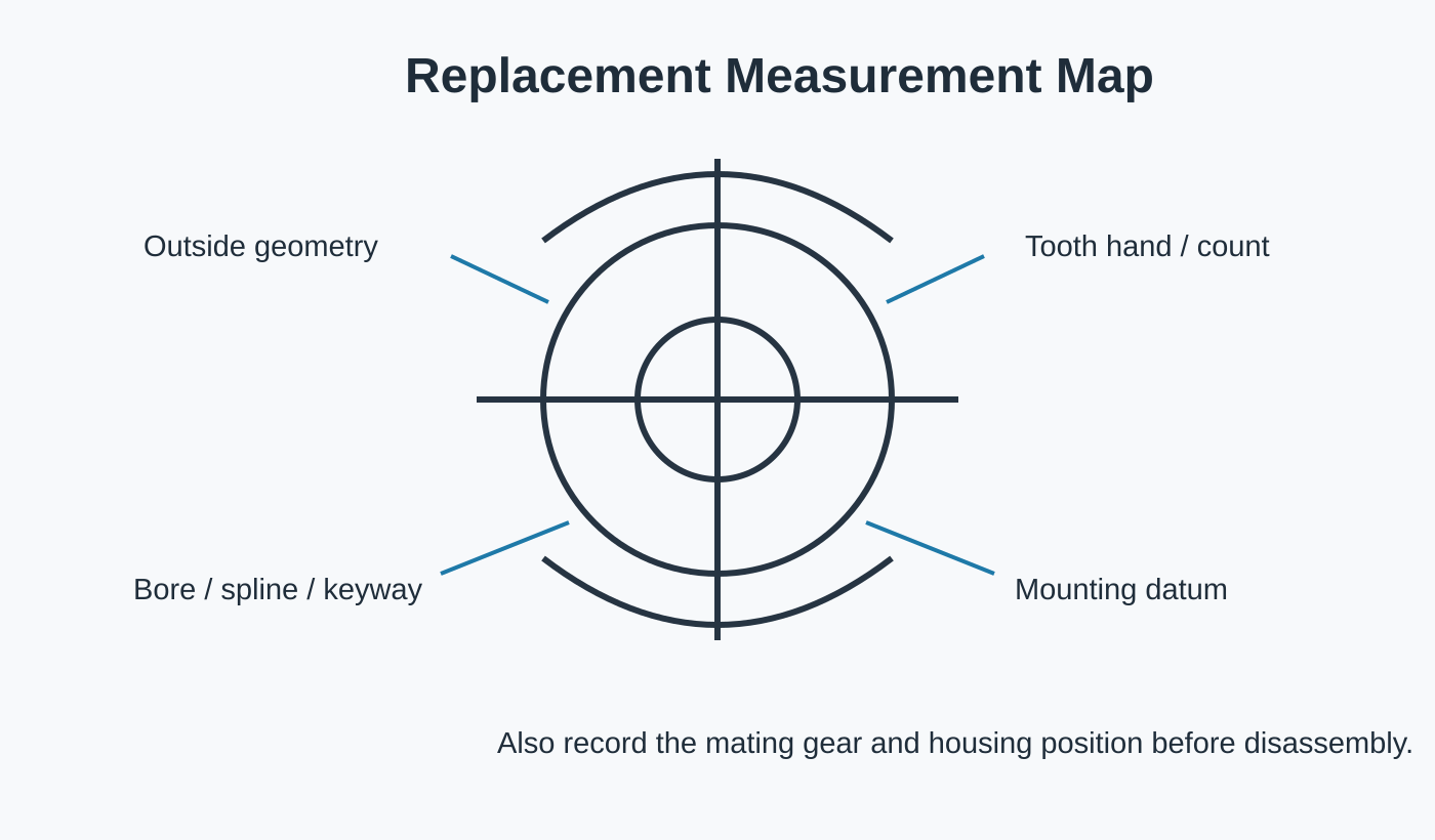
신원 확인 체크리스트
| 증거 | 이를 통해 확립될 수 있는 것 | 주의 |
|---|---|---|
| 결합 장치 | 비율/치아 개수, 손과 쌍의 관계 | 마모 상태를 점검하고 해당 부품이 실제로 동일한 조립체에 속하는지 확인하십시오. |
| 유산 그림 | 원래 형상, 인터페이스 및 승인 노트 | 개정 내역과 필드 수정 사항이 있는지 확인하십시오. |
| 부품 번호 | 신원 확인 및 역사적 참고 자료 | 숫자 하나만으로 현재의 기하학적 구조를 증명한다고 생각하지 마십시오. |
| 착용한 샘플 | 인터페이스 치수, 톱니 개수, 일반적인 형상 | 마모나 손상으로 인해 원래의 치아 또는 장착 상태가 가려질 수 있습니다. |
| 주택 측정 | 장착 위치 및 축 관계 | 정의된 기준점을 사용하고 손상된 베어링이나 헐거워진 부분을 기록하십시오. |
| 제거 전 사진 | 방향 및 조립 순서 | 크기/참조표를 포함하고 보는 방향을 표시하십시오. |
설계 형상과 손상 증거를 분리하십시오.
이빨 끝의 파손, 패임, 마모된 접촉면, 커진 구멍 등은 기존 부품의 사용 흔적을 보여줍니다. 이러한 흔적은 고장 원인 분석에 도움이 될 수 있지만, 교체 부품 도면에 자동으로 치수로 포함되어서는 안 됩니다. 손상되지 않은 부분과 결합 및 조립 데이터를 사용하여 새로운 규격 치수를 설정하십시오.
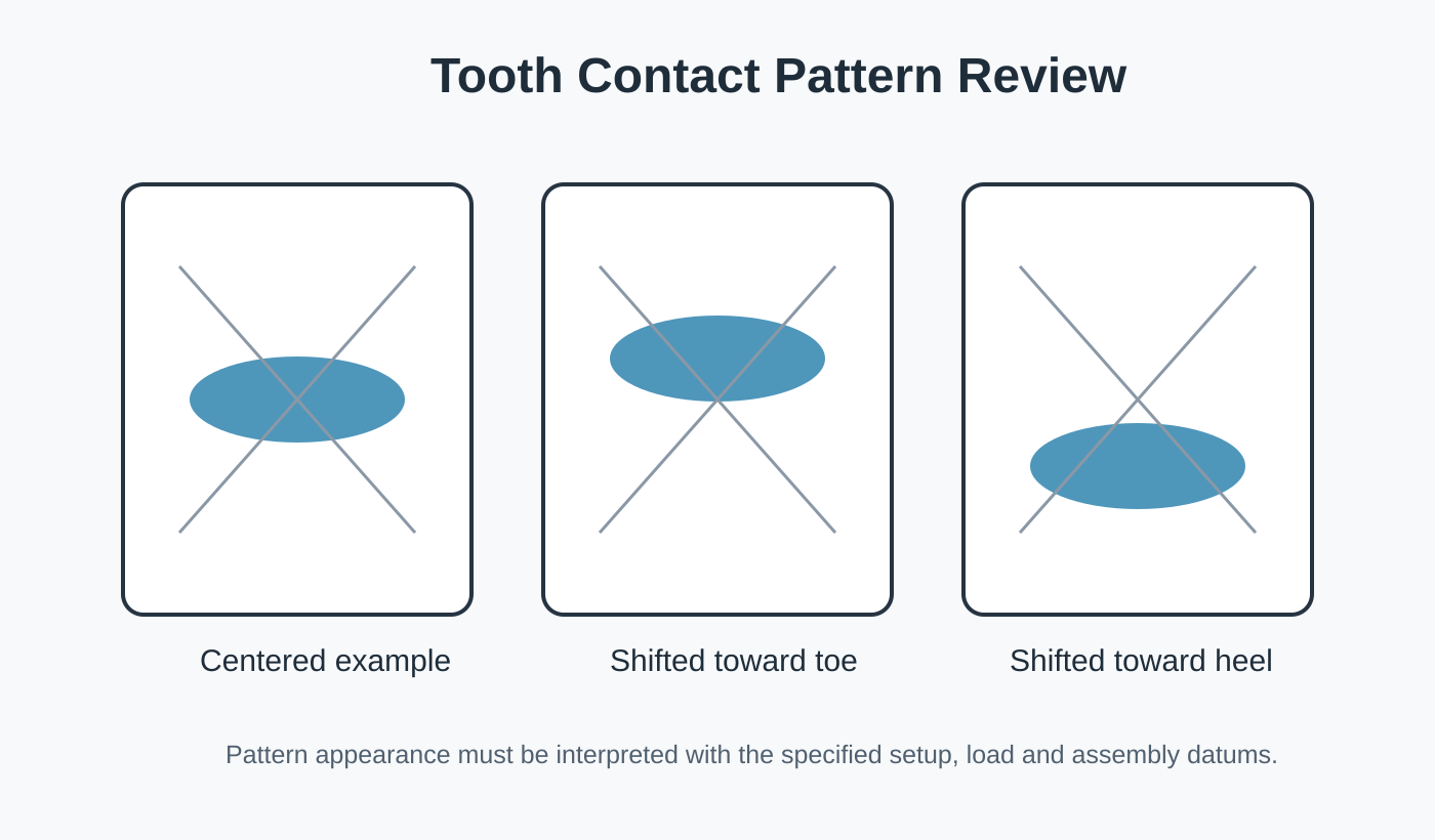
구성원 중 한 명만 교체할 수 있는 경우
맞물리는 기어를 계속 사용해야 하는 경우, 톱니 수, 원본 도면 또는 스캔본, 장착 위치, 육안으로 확인 가능한 상태 및 품질 정보 등 가능한 한 많은 신뢰할 수 있는 데이터를 제공하십시오. 호환성 검토가 완료되기 전까지는 정확한 호환성을 보장할 수 없습니다. 경우에 따라서는 하나의 부품을 교체하는 것보다 새 부품 한 쌍을 제작하는 것이 더 안전한 방법일 수 있습니다.
실물 샘플 포장
치아와 기준면이 추가 손상을 입지 않도록 보호하십시오. 기존 사용으로 인한 손상과 방향 설정을 위해 추가된 자국을 구분하십시오. 검토 과정에서 여러 부품이 혼합되지 않도록 각 샘플을 견적 요청서에 사용된 도면/참조 자료와 연결하는 간단한 포장 메모를 포함하십시오.
검토용 샘플을 발송하기 전에
유용한 표면과 표시가 드러날 정도로만 세척하고, 마모 흔적을 갈아내거나 광택을 내지 마십시오. 포장 시 톱니, 베어링 시트 및 기준면을 보호하십시오. 두 개의 부품이 한 쌍인 경우, 한 쌍으로 표시하고 방향 정보를 기재하십시오. 유사한 기어를 여러 개 배송하는 경우, 각 샘플에 견적 요청서 및 사진과 일치하는 고유 참조 번호를 부여하십시오.
간단한 "알려진 값/알려지지 않은 값" 목록을 포함하세요. 이 목록에는 어떤 값이 도면에서 가져온 것인지, 어떤 값이 마모된 샘플에서 측정된 것인지, 그리고 어떤 값이 아직 검토가 필요한지 명시해야 합니다. 이렇게 하면 측정값을 원래 설계 값으로 오인하는 것을 방지할 수 있습니다.
구매자들이 자주 묻는 질문
마모된 부품 하나만으로 교체해야 할까요?
때로는 충분히 신뢰할 만한 정보가 있지만, 그렇다고 단정해서는 안 됩니다. 짝, 주택 측정값 또는 기존 데이터는 원래의 짝을 복원하는 데 필수적일 수 있습니다.
두 명 모두 교체해야 할까요?
그것은 상태와 남아있는 짝이 얼마나 잘 정의되어 있는지에 따라 다릅니다. 기존 짝이 심하게 마모되었거나 기록이 없는 경우, 새로운 짝을 찾으면 불확실성을 줄일 수 있습니다.
부품 번호로 기어를 정확하게 식별할 수 있나요?
유용한 증거이지만, 수정 및 현장 변화가 있을 수 있습니다. 기준 자료와 현재 측정값, 그리고 교배 관계를 함께 고려하십시오.
장비 쌍, 도면 및 부하 정보를 하나의 견적 요청서에 포함하여 보내주십시오.
결합 관계 및 조립 기준점이 명확하게 정의될수록 구성 검토 속도가 빨라집니다.
주문 및 배송 안내
최소 주문 수량(MOQ)은 제품 유형, 제조 방식 및 총 주문 금액에 따라 유동적입니다. 적합한 신규 프로젝트의 경우 샘플 가격으로 1~5개의 샘플을 요청할 수 있습니다. 총 주문 금액이 약 1,500달러에 도달하면 여러 모델을 조합하여 주문할 수 있습니다. 1~2개 주문도 검토 가능하지만, 일반적으로 단가가 더 높습니다.
일반적인 계획 기간은 표준 부품의 경우 10~25영업일, 맞춤형 부품의 경우 20~45영업일, 프로젝트형 장비 또는 조립품의 경우 45~120영업일입니다. EXW, FOB, CIF 및 DAP 조건이 일반적으로 지원되며, FCA, CFR, CPT, CIP 및 DDP 조건은 선적 조건에 대해 협의 가능합니다.

























