Descripción
La integración del piñón cónico espiral con el eje reduce las uniones separadas, pero convierte los muñones de los cojinetes, los hombros, las estrías, las roscas y las marcas de referencia de los dientes en un único problema de fabricación. Por lo tanto, la solicitud de cotización debe mostrar el eje completo en lugar de tratar el cabezal del engranaje como una pieza aislada.
Mejor punto de partida: Un conjunto compacto donde los dientes del piñón y el eje se fabrican como un único componente controlado.
¿Para qué está diseñada esta familia de productos?
La principal ventaja es la integración. El principal riesgo es que un cambio en la interfaz del eje puede afectar la estrategia de referencia utilizada para el corte, el tratamiento térmico, el acabado y la inspección.
Utilice esta familia de engranajes cuando el eje y el piñón formen una sola pieza. Si el piñón es un engranaje perforado independiente, un juego de engranajes a medida o rectificado suele ser el punto de partida más adecuado.
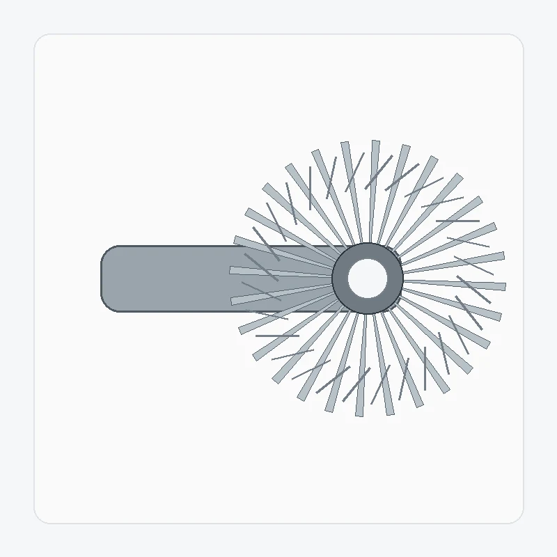
Tabla de especificaciones y solicitud de cotización
Para el eje del piñón cónico espiral, se confirman los valores numéricos exactos para la configuración solicitada. La tabla a continuación identifica los campos del plano y de la consulta que requieren un control explícito.
| Elemento de selección | Configuración | Nota de solicitud de cotización |
|---|---|---|
| Identidad de pareja | Par de engranajes cónicos espirales emparejados o componente individual específico para el proyecto. | Confirma el miembro de apareamiento y la relación de conducción. |
| Ángulo del eje | Específico del proyecto | Muestre la relación de ejes o el dibujo de ensamblaje. |
| Relación / recuento de dientes | Para dibujar o RFQ | Proporcione el número de dientes de ambas piezas dentales cuando se conozca. |
| Módulo / paso diametral | Para dibujar o RFQ | No haga la estimación basándose únicamente en el diámetro exterior. |
| Ángulo de presión | Confirmar la configuración solicitada | Utilice el plano o datos heredados fiables para los trabajos de sustitución. |
| Ángulo espiral y mano | Confirmar la configuración solicitada | Identifique la mano derecha/izquierda con una convención de visualización definida. |
| Distancia de montaje / juego | Específico del proyecto | Proporcionar datos de referencia de la vivienda y el rango objetivo cuando esté controlado. |
| Interfaz de orificio/estría/eje | Para dibujar o mostrar | Incluya los requisitos de chavetero, estándar de spline, muñones y datos de referencia. |
| Material / tratamiento térmico | Para revisión de dibujo o proyecto | Indique el grado, la dureza o los requisitos de la carcasa obligatorios, si están sujetos a control. |
| Acabado/calidad de los dientes | Para revisión de dibujo o proyecto | Requisitos de corte/acondicionamiento del estado y el estándar de aceptación o criterios de inspección. |
Las características del eje y los puntos de referencia de los engranajes deben medirse juntos.
Las referencias del muñón y del hombro se establecen con antelación para que los dientes del engranaje se puedan fabricar en relación con el eje. El tratamiento térmico y el posterior acabado deben proteger los requisitos de cojinete y montaje. La inspección final puede requerir correlacionar la excentricidad o la geometría de los dientes con los datos del eje especificados en el plano.
La representación visual técnica del eje del piñón cónico espiral sirve como ayuda para el análisis de las relaciones entre los componentes. El plano de producción controlado y el presupuesto aprobado constituyen la definición dimensional del pedido.
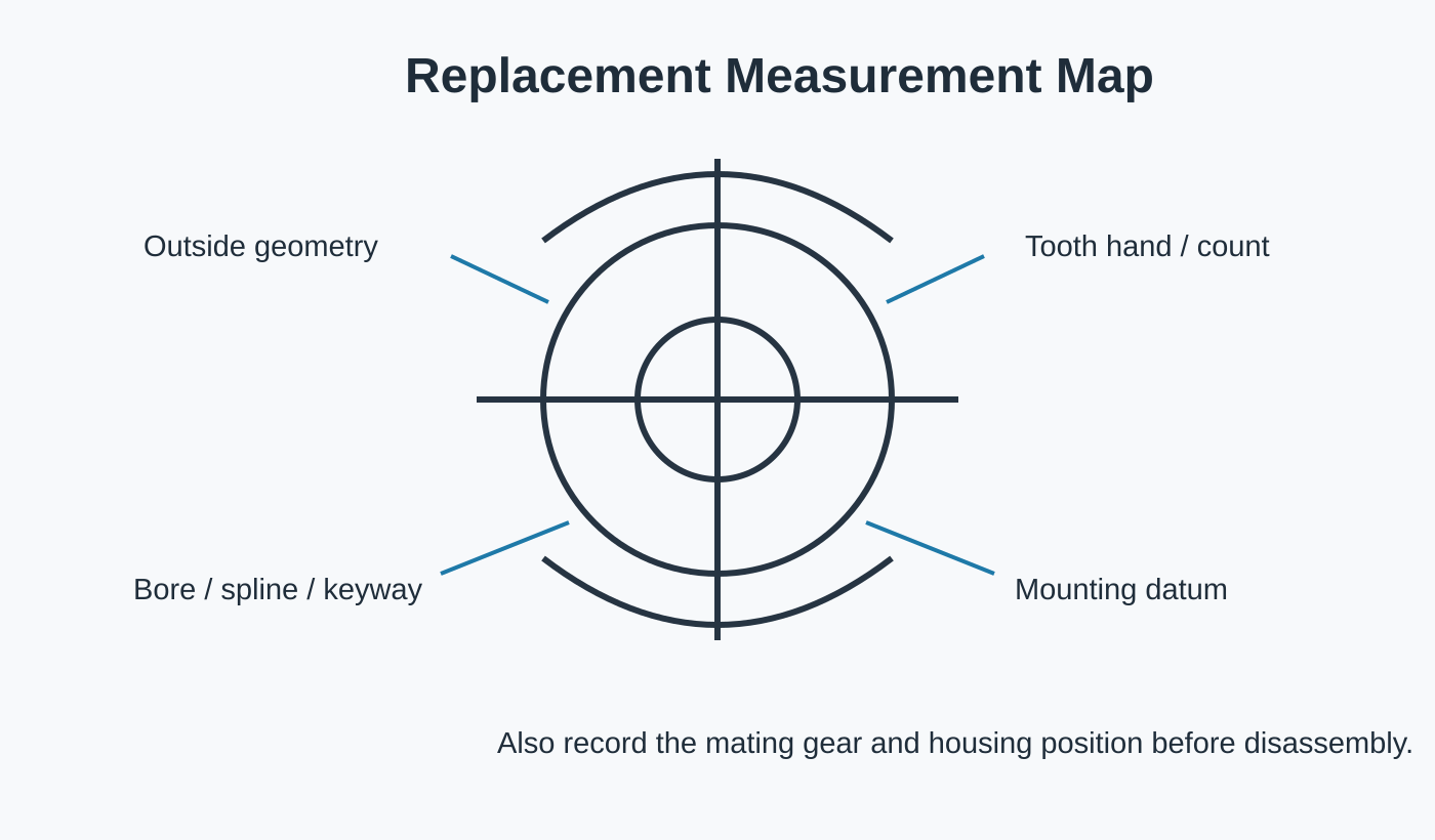
Interfaces y comprobaciones de ensamblaje

Miembro de apareamiento
Confirme qué engranaje es compatible con el componente y si ambos elementos están incluidos en el suministro.

Puntos de referencia y montaje
Muestre las superficies y los ejes que controlan la distancia de montaje, la posición del eje y el juego libre.

Ruta del material
Determinar los requisitos estatales de materiales y tratamientos térmicos e identificar las características que requieren mecanizado secundario.

Aceptación
Enumere las comprobaciones dimensionales, de calidad de los dientes, de excentricidad o de contacto que se requieren para la liberación.
Ajuste de aplicación típico
Cajas de engranajes compactas, accionamientos auxiliares para máquinas herramienta, mecanismos de automatización y conjuntos en los que el eje del piñón está soportado directamente por cojinetes en la máquina.
La solicitud de inspección debe enviarse junto con el plano siempre que pueda modificar la ruta del material, el acabado de los dientes, las suposiciones de soporte o los requisitos de inspección.

Máquinas herramienta CNC

Mecanismos de posicionamiento y accionamientos angulares donde la rigidez de montaje y la holgura son importantes.
Guía de solicitud →
Robótica y automatización

Mecanismos compactos de ejes que se cruzan, con requisitos de funcionamiento reversible y repetibilidad.
Guía de solicitud →
Sistemas de corte láser y pórtico

Transmisión con cambio de dirección alrededor de pórticos y equipos de posicionamiento automatizados.
Guía de solicitud →
Elevación de cargas pesadas y polipastos

Mecanismos de alta resistencia donde es necesario revisar los impactos, los arranques/paradas y la disposición de los soportes.
Guía de solicitud →
Maquinaria de precisión

Sistemas de precisión compactos con requisitos controlados de referencia, excentricidad y contacto.
Guía de solicitud →
Cajas de engranajes industriales

Etapas de la caja de cambios que distribuyen el par motor a través de conjuntos de ejes que se cruzan.
Guía de solicitud →Secuencia de fabricación e inspección
Revisar
Confirmar la revisión del dibujo, la identidad del par, las preguntas abiertas y las características críticas para la aceptación.
Plan
Defina la secuencia de mecanizado de la pieza en bruto, la pieza de referencia, el tallado de engranajes, el tratamiento térmico y el acabado.
Finalizar
Acabado completo de dientes e interfaces según la ruta solicitada.
Inspeccionar
Verifique las dimensiones y los criterios relacionados con los engranajes acordados para la configuración.
Qué incluir en la consulta
| Grupo RFQ | Detalle recomendado |
|---|---|
| Definición técnica | Dibujo actual, referencia de pares, relación/número de dientes, relación entre la mano y el eje |
| Asamblea | Diámetro del orificio/eje/estrías, cojinetes, puntos de referencia de la carcasa, distancia de montaje y juego libre si se controla. |
| Deber | Velocidad, espectro de par/carga, inversiones de sentido, impacto, entorno y lubricación. |
| Calidad | Registros de material, tratamiento térmico, acabado de los dientes, tolerancias e inspección |
| Comercial | Prototipo y cantidad repetida, destino, plazo objetivo y término comercial preferido |
Preguntas frecuentes
¿Puedo pedir solo uno de los miembros del par?
Para el eje del piñón cónico espiral, el suministro de un componente puede revisarse una vez que la unión esté completamente definida. Si se desconoce la unión existente, envíe su plano, medidas o el engranaje físico antes de liberar cualquier componente.
¿Es posible copiar directamente una muestra desgastada?
Una muestra desgastada del eje del piñón cónico espiral puede ayudar a la identificación, pero el desgaste no debe considerarse como la geometría original. Los planos antiguos, un componente de acoplamiento sin usar y las mediciones del conjunto proporcionan una base de reconstrucción más sólida.
¿Necesito elegir el material y el tratamiento térmico antes de la solicitud de cotización?
Cuando el diseño del eje del piñón cónico espiral determine el material o el tratamiento térmico, especifique el requisito exacto. Si estos elementos están disponibles, describa su función y márquelos para su revisión de selección, en lugar de utilizar un grado de otro engranaje.
¿Cómo se gestionan las muestras de pequeña cantidad?
Se pueden analizar pequeñas muestras de ejes de piñones cónicos espirales para identificar proyectos nuevos adecuados. Separe la cantidad de prototipos de la demanda prevista para que la configuración, la inspección y la producción posterior se planifiquen en función del volumen correcto.
Planificación comercial para su solicitud de cotización
Para la planificación de solicitudes de cotización, la cantidad mínima de pedido (MOQ) es flexible y depende del formato del producto, la ruta de procesamiento y el valor total del pedido. Se pueden evaluar nuevos proyectos adecuados para 1 a 5 muestras a precio de muestra. Se pueden combinar diferentes modelos cuando el total del pedido alcanza aproximadamente los 1500 USD. También se pueden considerar pedidos de 1 a 2 unidades, generalmente con un costo unitario más alto debido a que la configuración y la inspección se distribuyen entre una cantidad muy pequeña.
Para la planificación de entregas de solicitudes de cotización, los plazos habituales son de 10 a 25 días hábiles para piezas estándar, de 20 a 45 días hábiles para componentes personalizados y de 45 a 120 días hábiles para equipos o conjuntos de tipo proyecto. Se suelen aceptar los términos EXW, FOB, CIF y DAP; FCA, CFR, CPT, CIP y DDP pueden ser objeto de negociación para el envío y destino específicos.
Envíe el par de engranajes, el plano y la capacidad de carga en una sola solicitud de cotización.
Cuanto más claramente se definan la relación de acoplamiento y los datos de ensamblaje, más rápido se podrá revisar la configuración.
Guía para realizar pedidos y entregas
La cantidad mínima de pedido (MOQ) es flexible según el tipo de producto, el proceso de fabricación y el valor total del pedido. Los proyectos nuevos que cumplan con los requisitos pueden solicitar de 1 a 5 muestras a precio de muestra. Se pueden combinar diferentes modelos cuando el total del pedido alcance aproximadamente los 1500 USD. Se pueden revisar los pedidos de 1 a 2 unidades, aunque el costo unitario suele ser mayor.
Los plazos de planificación habituales son de 10 a 25 días hábiles para piezas estándar, de 20 a 45 días hábiles para componentes personalizados y de 45 a 120 días hábiles para equipos o conjuntos de tipo proyecto. Se suelen aceptar los términos EXW, FOB, CIF y DAP; para el envío, se pueden considerar FCA, CFR, CPT, CIP y DDP.

























