Product Description
Gearbox Reducer Machining Auto Spare Parts Metal Transmission Drive Steering Wheel Angular Right Angle Spiral Straight Bevel Gears Hypoid Pinion Shaft Gear
Features
1. High precision gear for smooth, quiet operation.
2. Flexible for custom-made requests.
3. Stable transmission, low impact, vibration and noise.
4. Heavy Load capability, more compact, but less complex.
Product Description
| Ürünler | Spur Gear, Helical Gear, Herringbone Gear, Spiral Bevel Gear, Straight Bevel Gear, Worm Gear, Shaft, Pinion |
| Module | M0.3-M10 |
| Precision grade | DIN6, DIN7, DIN8, DIN10 |
| Basınç açısı | 14.5 degree, 15 degree, 20 degree |
| Material | Medium Carbon Steel: 35#, 45# Carburizing Steel: 20CrMnTi, 20CrMnMo, 20CrMo Alloy Steel: 40Cr, 35CrMo, 42CrMo, 40CrNiMo Cast Iron: HT250, QT400 Copper, Stainless Steel, Brass, Nylon, POM, and so on |
| Heat treatment | Hardening & Tempering, Surface Quenching, Integral Quenching, Carburizing Quenching, Tempering, Normalizing, Nitriding |
| Surface treatment | Blacking, Polishing, Anodization, Chrome Plating, Zinc Plating, Nickel Plating |
| Application | Gearbox and reducer; Precision cutting machines, Lathes machines; Milling machines; Grinder machine; Automated mechanical systems; Automated warehousing systems. Gear hobbing machines, gear shapers, gear shaving machines, gear milling, gear grinding machines and many kinds of gear-related machines. |
| Machining process | Forging, Machining, Hobbing, Milling, Shaving, Grinding, Heat treatment… |
Detailed Photos
Our Advantages
Related Product
Company Profile
FAQ
Q: How to ship the bevel gear to us?
A: It is available by air, sea, or train.
Q: How to pay the money?
A: T/T and L/C are preferred, with different currencies, including USD, EUR, RMB, etc.
Q: How can I know if the product is suitable for me?
A: >1ST confirm drawing and specification >2nd test sample >3rd start mass production.
Q: Can I come to your company to visit?
A: Yes, you are welcome to visit us at any time.
| Application: | Machinery, Bevel Gearbox |
|---|---|
| Hardness: | Hardened Tooth Surface |
| Gear Position: | External Gear |
| Samples: |
US$ 50/Piece
1 Piece(Min.Order) | Order Sample bevel gear
|
|---|
| Customization: |
Available
| Customized Request |
|---|
.shipping-cost-tm .tm-status-off{background: none;padding:0;color: #1470cc}
|
Shipping Cost:
Estimated freight per unit. |
about shipping cost and estimated delivery time. |
|---|
| Payment Method: |
|
|---|---|
|
Initial Payment Full Payment |
| Currency: | US$ |
|---|
| Return&refunds: | You can apply for a refund up to 30 days after receipt of the products. |
|---|
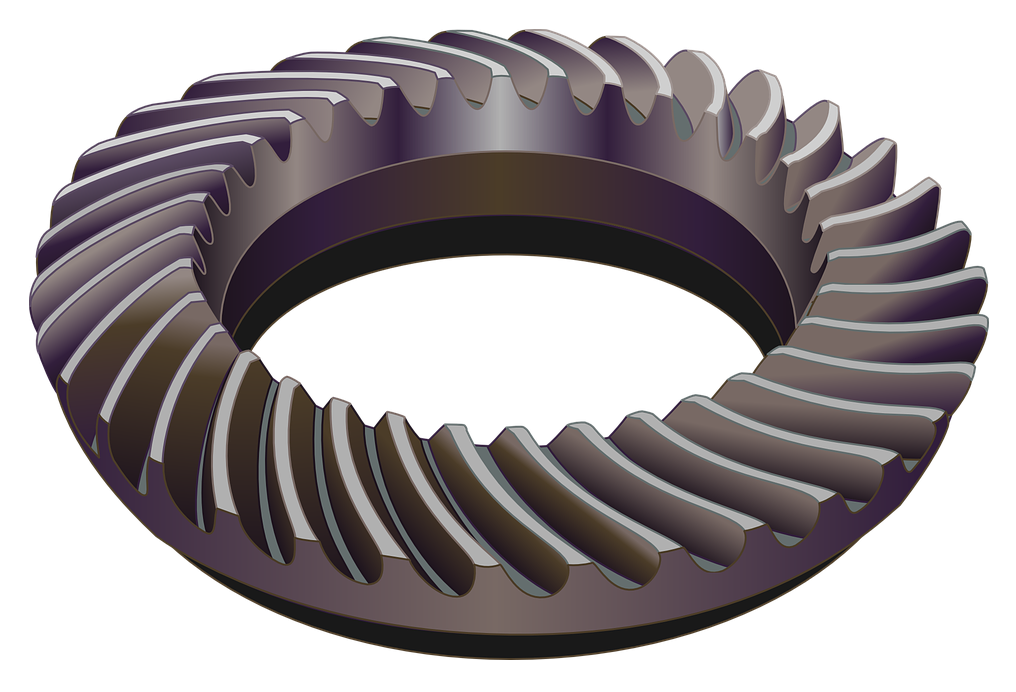
How do spiral gears handle variations in tooth engagement during operation?
Spiral gears are designed to handle variations in tooth engagement during operation effectively. The unique helical tooth arrangement of spiral gears allows them to accommodate these variations and provide several benefits. Here’s how spiral gears handle variations in tooth engagement:
- Gradual Engagement: One of the key advantages of spiral gears is their ability to achieve gradual tooth engagement. As the gears rotate, the helical shape of the teeth allows them to come into contact gradually, starting from one end of the gear to the other. This gradual engagement minimizes the impact and shock that would occur with sudden full tooth contact in other gear types. It results in smoother and quieter operation, reducing noise, vibrations, and stress on the gear system.
- Increased Tooth Contact Area: Spiral gears provide a larger tooth contact area compared to straight-cut or spur gears. The helical tooth profile extends the contact length along the gear face, distributing the load over multiple teeth at any given moment. This increased contact area enables spiral gears to handle higher loads and transmit torque more efficiently.
- Load Sharing: Due to the helical arrangement, spiral gears naturally distribute the load across multiple teeth. This load-sharing characteristic helps to minimize tooth wear and fatigue. As the gears rotate, different teeth come into contact, ensuring that the load is distributed evenly. This load sharing capability enhances the gear system’s durability and extends its service life, particularly in applications with fluctuating loads.
- Reduction of Side Thrust: Spiral gears generate an axial thrust force during operation. However, by using pairs of spiral gears with opposite helix angles, this side thrust force can be greatly reduced or even eliminated. When paired gears with opposite helix angles mesh together, the axial thrust forces cancel each other out. This eliminates the need for additional thrust bearings or complex gear arrangements to counteract the axial forces, simplifying the gear system design.
- Improved Lubrication: The helical tooth profile of spiral gears promotes better lubrication. The continuous sliding motion between the teeth creates a pumping action that helps distribute lubricant along the tooth surfaces. This improved lubrication reduces friction, heat generation, and wear, enhancing the overall efficiency and longevity of the gear system.
These features of spiral gears—gradual engagement, increased tooth contact area, load sharing, reduction of side thrust, and improved lubrication—make them highly effective in handling variations in tooth engagement during operation. Spiral gears are commonly used in various applications such as automotive transmissions, industrial machinery, and power generation systems, where smooth and reliable power transmission is crucial.
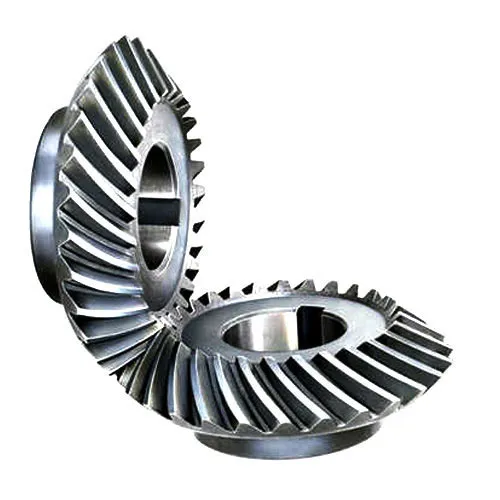
What is the impact of helix angle on spiral gear performance?
The helix angle plays a crucial role in determining the performance characteristics of spiral gears. It affects various aspects of gear operation and functionality. Here’s the impact of the helix angle on spiral gear performance:
- Load-Carrying Capacity: The helix angle influences the load-carrying capacity of spiral gears. A larger helix angle results in a more pronounced helical shape of the teeth, providing a larger contact area between the gears. This increased contact area allows spiral gears to distribute the load over more teeth, thereby increasing their load-carrying capacity. Gears with larger helix angles can handle higher loads and transmit more torque.
- Smoothness of Operation: The helix angle significantly affects the smoothness of gear operation. A larger helix angle leads to a more gradual tooth engagement as the gears mesh. This gradual engagement reduces impact and vibration during gear meshing, resulting in smoother operation and reduced noise levels. Spiral gears with larger helix angles are known for their quiet operation and enhanced gear meshing characteristics.
- Efficiency and Power Transmission: The helix angle also influences the efficiency of power transmission in spiral gears. A larger helix angle reduces sliding friction between the teeth during meshing. This reduction in friction results in improved power transmission efficiency and reduced energy losses. Gears with larger helix angles are more efficient in transmitting power, making them suitable for applications where power efficiency is a critical factor.
- Axial Thrust and Thrust Load: The helix angle affects the axial thrust and thrust load in spiral gears. Axial thrust is the force generated in the axial direction due to the helical tooth arrangement. A larger helix angle produces a higher axial thrust, while a smaller angle generates a lower axial thrust. The axial thrust must be considered and managed in gear design to ensure proper gear support and minimize the need for additional thrust bearings.
- Contact Pattern and Gear Meshing: The helix angle influences the contact pattern between the teeth during gear meshing. A larger helix angle shifts the contact pattern across the tooth face, allowing for more even distribution of the load and reduced stress concentration. The contact pattern also affects the gear meshing characteristics, such as tooth wear and noise generation. Proper selection of the helix angle ensures optimal contact pattern and improved gear meshing performance.
The choice of helix angle in spiral gears depends on the specific application requirements, including load capacity, smoothness of operation, power transmission efficiency, and axial thrust considerations. By selecting an appropriate helix angle, engineers can optimize spiral gear performance for different applications, ensuring reliable and efficient gear operation.
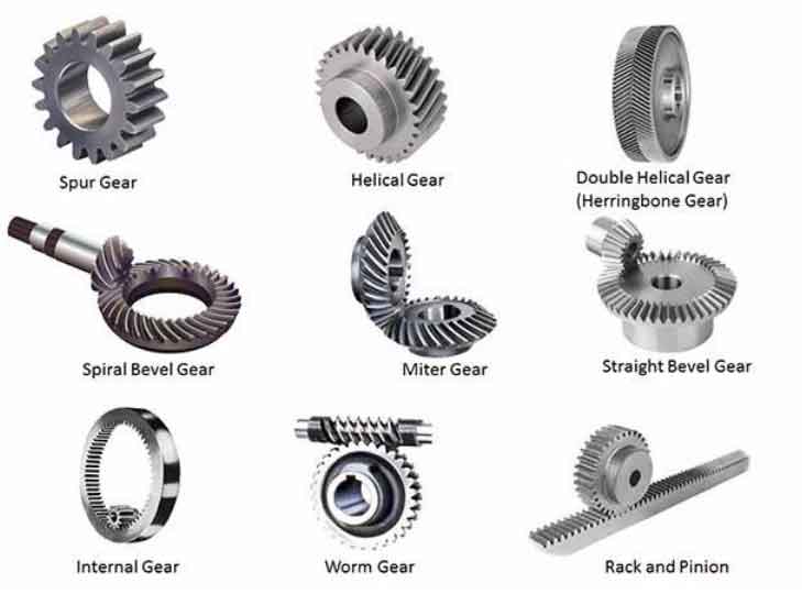
What are spiral gears and how are they used in machinery?
Spiral gears are a type of cylindrical gears with teeth that are curved in a spiral pattern. Unlike straight-cut gears, which have teeth that are parallel to the gear axis, spiral gears have teeth that are angled or helical. This helical tooth arrangement provides several advantages in terms of performance and noise reduction.
Spiral gears are commonly used in machinery for various applications due to the following reasons:
- Smooth and Quiet Operation: The helical tooth arrangement of spiral gears enables gradual tooth engagement, resulting in smoother and quieter operation compared to straight-cut gears. The angled teeth allow for gradual contact, reducing noise and vibration during gear meshing.
- Increased Load Capacity: The helical tooth design of spiral gears distributes the load over multiple teeth, increasing the load-carrying capacity. This makes spiral gears suitable for applications that require high torque transmission and heavy-duty operations.
- Improved Efficiency: The helical tooth arrangement of spiral gears helps in minimizing sliding friction between the teeth. This results in a higher level of efficiency compared to straight-cut gears, as there is reduced power loss due to friction during gear operation.
- Axial Thrust Compensation: Spiral gears can be designed with opposite helix angles on mating gears, which helps in canceling out the axial thrust generated during gear meshing. This feature eliminates the need for additional thrust bearings, simplifying the gear design and reducing complexity.
- Versatility: Spiral gears can be manufactured in various configurations, including spur, helical, and double helical designs. This versatility allows for their application in a wide range of machinery, including automotive systems, industrial equipment, and power transmission systems.
In machinery, spiral gears are commonly used in applications that require smooth operation, high load capacity, and efficient power transmission. Some examples include gearboxes, automotive differentials, machine tools, and heavy-duty industrial machinery.
Overall, the unique tooth geometry of spiral gears makes them a preferred choice in many machinery applications, offering improved performance, reduced noise, and enhanced load-carrying capabilities.


editor by CX 2023-10-12
China wholesaler CZPT Truck Cw520 Suitable Ratio 6/41 Spiral Bevel Gear with high quality
Product Description
Product Description
| Car Fitment | Nissan |
| OE No. | 38110-90502 |
| Speed Ratio | 6/41 |
| Type | Differential Gear |
| Ring Gear Outer Diameter | 428mm |
| Material | 20CrMnTi/ 8620 |
| Hardness | HRC58-62 |
| Treatment | Carburizing,Hardening, tempering,high frequency treatment,black coating,zincing,nickelage |
Company Profile
HangZhou CHINAMFG Machinery is a professional manufacture of spiral bevel gear. The company has CNC milling machine, the GLEASON milling machine, rolling inspection machine, gear measuring center, a full set of metallographic analysis, inspection equipment and other related advanced equipment.
Our company owns gear measuring center equipped with advanced testing machines such as contourgraph, universal measuring microscope and full set netlaaographic analysis detector. According to various technical requirements and through procedures of sampling, special inspection and re-examination, multi-indexes of gears like observation, measurement and tracking can be completed.
With our high quality products, high credibility and trusty cooperation, aiming to be a highly specialized gear manufacturer of high level and all-directional service,we are looking CHINAMFG to your business negotiation and our promising cooperation.
FAQ
Q1: Are your products standard?
A: Our model is standard, if you have specific demand, pls tell us.
Q2: What is you main categories?
A: CHINAMFG truck parts, CHINAMFG truck parts, Hino truck parts, CHINAMFG truck parts.
Q3: If we don’t find what we want on your website, what should we do?
A: You can email us the descriptions and pictures of the products you need, we will check whether we have them.
B: We develop new items every month, and some of them have not been uploaded to website in time. Or you can send us sample by express, we will develop this item for bulk purchasing.
Q4: What is your terms of payment?
A: T/T 30% as deposit, and 70% before delivery. We’ll show you the photos of the products and packages before you pay the balance
Q5:Do you test all your goods before delivery?
Yes, we have 100% test before delivery
| Application: | Motor, Electric Cars, Motorcycle, Machinery, Agricultural Machinery |
|---|---|
| Hardness: | Hardened Tooth Surface |
| Gear Position: | External Gear |
| Manufacturing Method: | Cut Gear |
| Toothed Portion Shape: | Curved Gear |
| Material: | Cast Steel |
| Customization: |
Available
| Customized Request |
|---|
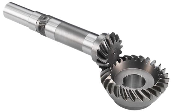
Can spiral gears be used in automotive applications?
Yes, spiral gears can be used in automotive applications and provide several advantages in this context. Here’s why spiral gears are suitable for automotive applications:
- Noise Reduction: Spiral gears offer significant noise reduction compared to other gear types, making them ideal for automotive applications that require quiet operation. The helical tooth arrangement minimizes gear meshing noise by providing gradual tooth engagement, reducing impact and vibration.
- Smooth Operation: The gradual tooth engagement of spiral gears also contributes to smoother gear operation. This smoothness helps to improve shifting performance, leading to enhanced driving comfort and reduced wear on transmission components.
- High Load Capacity: Spiral gears have a high load-carrying capacity, which is important in automotive applications where gears are subjected to varying loads. They can handle the torque requirements of transmissions and differential systems effectively.
- Efficient Power Transmission: Spiral gears offer efficient power transmission due to their helical tooth profile. This efficiency helps optimize fuel consumption and overall vehicle performance. By reducing energy losses through improved tooth contact and reduced sliding friction, spiral gears contribute to better power transfer.
- Durability and Reliability: Automotive applications demand gears that can withstand continuous use and provide long-term reliability. Spiral gears are known for their durability, thanks to load distribution and reduced stress concentration. They can maintain reliable performance even under challenging conditions.
- Axial Thrust Compensation: Spiral gears can be designed with opposite helix angles to cancel out axial thrust. This feature is particularly beneficial in automotive applications where minimizing axial forces is crucial. It simplifies gear design and reduces the need for additional components, enhancing space efficiency.
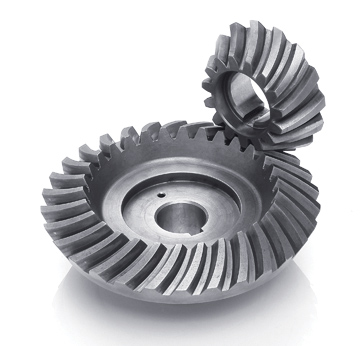
Considering their noise reduction capabilities, smooth operation, high load capacity, efficient power transmission, durability, and axial thrust compensation, spiral gears are well-suited for various automotive applications. They are commonly used in transmissions, differentials, and other drivetrain components to ensure reliable and efficient power transfer, contributing to overall vehicle performance and comfort.
How do you calculate the gear ratio in a spiral gear system?
The gear ratio in a spiral gear system can be calculated by comparing the number of teeth on the driving gear (pinion) to the number of teeth on the driven gear (gear). The gear ratio represents the ratio of the angular velocity (speed) of the driving gear to the angular velocity of the driven gear. Here’s the formula to calculate the gear ratio:
Gear Ratio = Number of Teeth on Driven Gear / Number of Teeth on Driving Gear
For example, consider a spiral gear system where the driving gear (pinion) has 20 teeth, and the driven gear (gear) has 40 teeth. The gear ratio can be calculated as follows:
Gear Ratio = 40 / 20 = 2
In this example, the gear ratio is 2, which means the driven gear will rotate at half the speed of the driving gear. This calculation assumes that the gears have the same module (gear size) and that there are no additional gear stages in the system.
It’s important to note that the gear ratio determines the speed and torque relationship between the driving and driven gears. A gear ratio greater than 1 (e.g., 2, 3, etc.) indicates a reduction in speed and an increase in torque, while a gear ratio less than 1 (e.g., 0.5, 0.75, etc.) indicates an increase in speed and a reduction in torque.
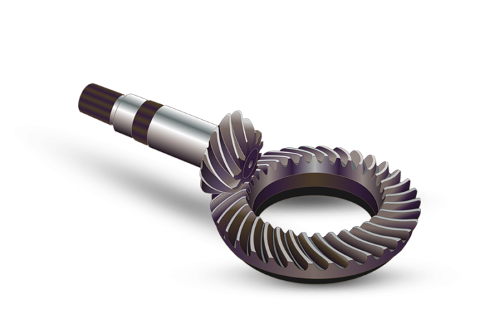
When working with spiral gears, it’s essential to consider the helix angle and axial thrust in addition to the gear ratio to ensure proper gear design and performance.
Can you explain the advantages of using spiral gears over other gear types?
Spiral gears, also known as helical gears, offer several advantages over other gear types. These advantages stem from their unique design and characteristics. Here are some key advantages of using spiral gears:
- Smooth and Quiet Operation: The helical tooth arrangement in spiral gears enables gradual tooth engagement, resulting in smoother and quieter operation compared to straight-cut gears. The angled teeth allow for gradual contact, reducing impact and noise during gear meshing.
- High Load Capacity: Spiral gears can handle higher loads compared to straight-cut gears. The helical tooth design distributes the load over multiple teeth, increasing the load-carrying capacity and providing improved strength. This makes spiral gears well-suited for applications that require the transmission of high torque or the handling of significant loads.
- Efficient Power Transmission: Spiral gears exhibit higher efficiency compared to straight-cut gears. The helical tooth arrangement helps minimize sliding friction between the teeth, resulting in reduced power losses due to friction during gear operation. This efficiency is crucial in applications where power transmission needs to be optimized, and energy losses need to be minimized.
- Reduced Noise and Vibration: The gradual tooth engagement in spiral gears leads to reduced impact and vibration during gear meshing. This results in quieter operation, making spiral gears suitable for applications where noise reduction is important, such as in precision machinery or noise-sensitive environments.
- Axial Thrust Compensation: Spiral gears can be designed with opposite helix angles on mating gears, which helps cancel out the axial thrust generated during gear meshing. This feature eliminates the need for additional thrust bearings, simplifying the gear design and reducing complexity.
- Versatility and Adaptability: Spiral gears can be manufactured in various configurations, including spur, helical, and double helical designs. This versatility allows for their application in a wide range of machinery and systems, providing flexibility in gear design and usage.
These advantages make spiral gears a preferred choice in many applications where smooth operation, high load capacity, efficient power transmission, reduced noise, and versatility are important considerations.
editor by CX 2023-10-11
China Good quality High Accuracy Spur Gear Hardened Cylindrical Gear Hardened Cementation HRC 60 gear ratio calculator
Product Description
1) Competitive price and good quality
2) Used for transmission systems.
3) Excellent performance, long using life
4) Could be developed according to your drawings or data sheet
5) Pakaging:follow the customers’ requirements or as our usual package
6) Brand name: per every customer’s requirement.
7) Flexible minimum order quantity
8) Sample can be supplied
Detailed Photos
Uygulamalar
Mainly used in the mining, metallurgical, cement, chemicals,construction, buiding materials,
electric power, telecommunictions, textiles, and transportation departments.
Such as:
1. conveyor:Belt conveyor,AFC conveyor, chain conveyor, screw conveyor.
2. Pum:Water pump, oil pump, slush pump, etc.
3. Fan: Draft fan, fanner, boil fan, etc.
4. Excator:bucket excavator bucket, wheel excavators .
5. Crane:Tower crane, gantry crande, bridge crane.
6. Others:Various elevators, coal plough, ball mill, crusher, recreation machine.
7. Blender equipment, centrifuger, washer, leather-making machine, machine for recreation park mixer wire drawing machine.Extruder, dregs crusher of boiler.
8. Plastic feeder, rubber smelling machine, etc.
Packaging & Shipping
| Packing | Standard suitable package / Pallet or container. Polybag inside export carton outside, blister and Tape and reel package available. If customers have specific requirements for the packaging, we will gladly accommodate. |
| Shipping |
10-20working days ofter payment receipt comfirmed (based on actual quantity). Professional goods shipping forward. |
Company Profile
FAQ
Q: Are you trading company or manufacturer?
A: We are factory.
Q: How long is your delivery time?
A: Generally it is 5-10 days if the goods are in stock. or it is 15-20 days if the goods are not in stock, it is according to quantity.
Q: Do you provide samples ? is it free or extra ?
A: Yes, we could offer the sample for free charge but do not pay the cost of freight.
Q: What is your terms of payment ?
A: Payment=1000USD, 30% T/T in advance ,balance before shippment.
We warmly welcome friends from domestic and abroad come to us for business negotiation and cooperation for mutual benefit. To supply customers excellent quality products with good price and punctual delivery time is our responsibility.
| Application: | Motor, Electric Cars, Motorcycle, Machinery, Agricultural Machinery |
|---|---|
| Hardness: | Hardened Tooth Surface/Soft Tooth Surface |
| Gear Position: | External Gear |
| Manufacturing Method: | Sintered Gear |
| Toothed Portion Shape: | Spur/Spiral/Bevel/Worm |
| Material: | Nylon, Plastic,Alloy,Copper,Stainless Steel,Steel |
| Samples: |
US$ 0/Piece
1 Piece(Min.Order) | |
|---|
| Customization: |
Available
| Customized Request |
|---|
How do spiral gears contribute to reducing noise and vibration?
Spiral gears contribute significantly to reducing noise and vibration in gear systems. Their unique design and characteristics help minimize unwanted sound and vibrations. Here’s how spiral gears achieve noise and vibration reduction:
- Gradual Tooth Engagement: Spiral gears have a helical tooth arrangement, which results in gradual tooth engagement as the gears mesh. Unlike spur gears with instantaneous full tooth contact, the helical teeth of spiral gears gradually come into contact, reducing the impact and shock during gear meshing. This gradual engagement helps to minimize noise and vibration.
- Improved Contact Pattern: The helical tooth profile of spiral gears produces a favorable contact pattern between the teeth. The contact pattern is more evenly distributed across the tooth face compared to spur gears, which reduces stress concentration and potential noise generation. The improved contact pattern contributes to smoother and quieter gear operation.
- Load Distribution: Spiral gears distribute the load over multiple teeth due to their helical shape. This load distribution helps to minimize localized stresses and reduces the risk of tooth breakage or pitting, which can contribute to noise and vibration. By spreading the load across a larger contact area, spiral gears ensure smoother and more stable gear operation.
- Reduced Sliding Friction: The sliding friction between gear teeth can generate noise and vibration. Spiral gears, with their helical tooth profile, exhibit reduced sliding friction compared to spur gears. The sliding motion is distributed along the helical path, resulting in smoother tooth contact and reduced friction-induced noise and vibration.
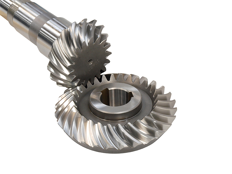
Collectively, these factors—gradual tooth engagement, improved contact pattern, load distribution, and reduced sliding friction—contribute to the noise and vibration reduction achieved by spiral gears. This makes them particularly suitable for applications where quiet operation and minimal vibration are essential, such as precision machinery, automotive transmissions, and other noise-sensitive environments.
What are the benefits of using spiral gears in high-torque applications?
Spiral gears, also known as helical gears, offer several benefits when used in high-torque applications. These advantages make them well-suited for transmitting large amounts of torque efficiently and reliably. Here are the key benefits of using spiral gears in high-torque applications:
- High Load Capacity: Spiral gears are designed to handle high loads and transmit significant amounts of torque. The helical tooth arrangement allows for load distribution across multiple teeth, reducing stress concentration on individual teeth. This design feature enables spiral gears to withstand the heavy forces encountered in high-torque applications.
- Smooth and Efficient Power Transmission: The helical shape of the teeth in spiral gears enables smooth and continuous contact between the mating gears. This gradual tooth engagement results in reduced impact and vibration during gear meshing. Additionally, the helical tooth profile minimizes sliding friction, leading to efficient power transmission and reduced energy losses, which is particularly important in high-torque applications where power efficiency is crucial.
- Reduced Noise and Vibration: The gradual tooth engagement and improved contact pattern in spiral gears contribute to reduced noise and vibration during operation. The helical tooth arrangement helps to distribute the load more evenly, minimizing dynamic forces and resulting in quieter gear operation. This is especially beneficial in high-torque applications where noise reduction is desired, such as precision machinery or noise-sensitive environments.
- Axial Thrust Compensation: Spiral gears can be designed with opposite helix angles on mating gears, which helps cancel out the axial thrust generated during gear meshing. This feature is particularly advantageous in high-torque applications where managing axial forces is critical. By eliminating or reducing the axial thrust, spiral gears simplify the gear design and reduce the need for additional components, such as thrust bearings.
- Reliability and Durability: The robust design of spiral gears, combined with their ability to handle high loads and transmit torque efficiently, contributes to their overall reliability and durability in high-torque applications. The gradual tooth engagement, load distribution, and reduced friction help minimize wear and extend the service life of the gears, ensuring long-term performance under demanding conditions.
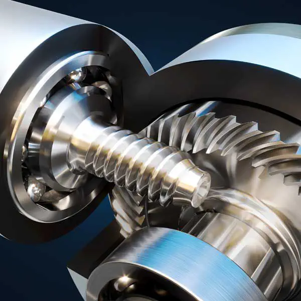
These benefits make spiral gears an excellent choice for high-torque applications where reliable and efficient power transmission, smooth operation, reduced noise, and durability are essential requirements.
How do spiral gears differ from other types of gears?
Spiral gears, also known as helical gears, have distinct differences compared to other types of gears. These differences primarily stem from the helical tooth arrangement in spiral gears. Here’s how spiral gears differ from other gear types:
- Helical Tooth Arrangement: Spiral gears have teeth that are curved in a spiral pattern, forming a helix. This is different from straight-cut gears, which have teeth parallel to the gear axis, or bevel gears, which have teeth on conical surfaces. The helical tooth arrangement in spiral gears provides various advantages such as smoother operation, increased load capacity, and improved efficiency.
- Gradual Tooth Engagement: Due to the helical tooth arrangement, spiral gears have a gradual tooth engagement as the gears rotate. This gradual contact reduces impact and noise during gear meshing, resulting in smoother and quieter operation compared to straight-cut gears.
- Axial Thrust Compensation: Spiral gears can be designed with opposite helix angles on mating gears, which helps in canceling out the axial thrust generated during gear meshing. This feature eliminates the need for additional thrust bearings and simplifies the gear design, reducing complexity.
- Load Distribution: The helical tooth arrangement in spiral gears allows the load to be distributed over multiple teeth. This enables spiral gears to handle higher torque transmission and carry heavier loads compared to straight-cut gears.
- Efficiency: Spiral gears exhibit higher efficiency due to reduced sliding friction between the teeth. The helical tooth arrangement helps minimize sliding friction, resulting in lower power losses during gear operation.
- Versatility: Spiral gears can be manufactured in various configurations, including spur, helical, and double helical designs. This versatility allows for their application in a wide range of machinery and systems, providing flexibility in gear design and usage.
These differences make spiral gears well-suited for applications that require smooth operation, high load capacity, and efficient power transmission. They are commonly used in gearboxes, automotive differentials, machine tools, and various industrial machinery.
In summary, spiral gears stand out from other gear types due to their helical tooth arrangement, resulting in smoother operation, increased load capacity, improved efficiency, and versatility.
editor by CX 2023-10-09
China supplier China Spiral Bevel Gear Manufacturers straight bevel gear
Product Description
Company Profiles
-We are a leading gear motor manufacturer
ZHangZhoug Xihu (West Lake) Dis.hai Reducer is a leading manufacturer of gear motor and gearbox.
Since 1991, we have specialized in manufacturing a wide range of gear motor and gear box including:
- helical gear motor
- helical bevel gear motor
- parallel shaft helical gear motor
- helical worm gear motor
- hoist drive
- heavy-duty helical gearbox
- heavy-duty helical bevel gearbox
- gear motor for car parking system
- sprial bevel gearbox
Product Description
HD series spiral bevel gear unit is composed with a pair of spiral bevel gears.
Mounting position: the shape of the housing is a regular hexahedron, which can be installed in different ways.
Thechnical data:
motor power: 0.12KW~160KW
rated output torque: 3N·m~1000N·m
gear ratio:1~5
Product Show
Product Specification
| Product features | |||||||
| 1. Spiral bevel gearbox with various types are standardized, all ratios of 1:1, 1.5:1, 2:1, 2.5:1, 3:1, 4:1, 5:1 are actual ones, and average efficiency is 98%. | |||||||
| 2. Gear can rotate in both directions and transmit smoothly, low noise, light vibration and high load capacity. | |||||||
| 3. Modular design, has many ratios, motor combinations, mounting positions and structures to meet the different working conditions. | |||||||
| 4.Gears are made of high quality alloy steel, the surface hardness can be HRC58-62 after heat treatment (such as carburizing and quenching), the precision is 5-6 grades. | |||||||
| 5.Using computer gear tooth modification technology to improve load capacity of reducer. | |||||||
| There are a single axis, double horizontal shaft, vertical single, double longitudinal axis as optionals. It is widely used in metallurgy, mining, petrochemical, tobacco, ceramics, rubber, grain and oil food, beer beverage, transportation, and domestic emerging logistics equipment, parking equipment, environmental protection and other industries. The spiral bevel gears can be positive and negative, low speed or high speed.. | |||||||
| General Technical data | |||||||
| Housing material | HT250 high-strength Cast Iron | ||||||
| Housing hardness | HBS190-240 | ||||||
| Pinion material | 20CrMnTiH | ||||||
| Gear material | 20CrMnTiH | ||||||
| Surface hardness of gears | HRC58°~62 ° | ||||||
| Gear core hardness | HRC33~40 | ||||||
| Input/output shaft material | 40CrMnTiH | ||||||
| Input / Output shaft hardness | HRC25~30 | ||||||
| Machining precision of gears | accurate grinding, 6~7 Grade | ||||||
| Lubricating oil | L-CKC220 (GB 5903-95) | ||||||
| Heat treatment | tempering, cementiting, quenching, etc. | ||||||
| Efficiency | 98% | ||||||
| Noise (MAX) | 60~68dB | ||||||
| Temp. rise (MAX) | 40°C | ||||||
| Temp. rise (Oil)(MAX) | 50°C | ||||||
| Vibration | ≤20µm | ||||||
| Backlash | ≤20Arcmin | ||||||
| Brand of bearings | China Top brand C&U,LYC,TMB or other brands requested, SKF….. | ||||||
| Brand of oil seal | CTY— ZheJiang or other brands requested | ||||||
Package
Plastic bag + wooden carton
Certificate
FAQ
Q: Can you print other colors?
Yes. Customized color can be printed on the gear motor according to your requirements.
Q: Is that factory price?
Yes. We assure you all prices are based on factory.
Q: What is the life span? what is the guarantee
The lifespan of gear motor can reach 5-20 years depending on different working conditions .The guarantee time is 1 year after delivery.
Q: What documents are available?
A full range documents including structural drawings, packing list, installation manual and relative certificates can be provided. Moreover, customs declaration is provided. We provide one-stop service for you.
Q: Is it able to customized?
yes, we could re-design and produce the gear motor as your requirements if the quantity is large.
| Application: | Motor, Machinery, Nuclear Industry |
|---|---|
| Hardness: | Hardened Tooth Surface |
| Installation: | Horizontal Type |
| Layout: | Coaxial |
| Gear Shape: | Spiral |
| Step: | Three-Step |
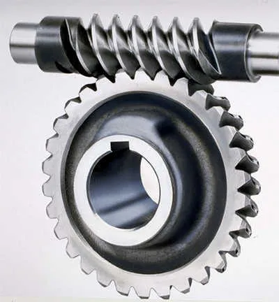
How do spiral gears handle changes in direction and torque transmission?
Spiral gears are well-suited to handle changes in direction and torque transmission due to their unique design and characteristics. Here’s how spiral gears handle these aspects:
- Smooth Direction Changes: Spiral gears excel at transmitting power smoothly even during changes in direction. The helical tooth arrangement allows for gradual tooth engagement and disengagement as the gears rotate. This gradual engagement minimizes the impact and shock typically associated with sudden direction changes in gear systems. As a result, spiral gears provide smoother and more reliable power transmission during both forward and reverse rotations.
- Torque Transmission: Spiral gears are capable of transmitting high torque loads. The helical tooth profile and increased tooth contact area allow for efficient torque transfer between the driving and driven gears. The load distribution across multiple teeth helps to minimize stress concentration and maximize the gear’s torque-carrying capacity. This makes spiral gears suitable for applications requiring high torque transmission, such as heavy machinery and industrial equipment.
- Axial Thrust Compensation: Spiral gears can be designed with opposite helix angles on mating gears, resulting in axial thrust cancellation. This feature is particularly beneficial when dealing with bidirectional torque transmission. By canceling out the axial thrust, spiral gears can operate with reduced axial forces, ensuring smoother gear operation and minimizing the need for additional thrust bearings or complicated gear arrangements.
- Load Sharing: Spiral gears naturally distribute the load across multiple teeth due to their helical tooth arrangement. This load sharing capability helps to minimize tooth wear and fatigue, ensuring long-term durability and reliability, especially when subjected to varying torque conditions. By distributing the load, spiral gears can handle torque variations more effectively and maintain uniform tooth contact, resulting in improved performance and extended gear life.
These characteristics of spiral gears—smooth direction changes, efficient torque transmission, axial thrust compensation, and load sharing—make them highly suitable for applications that require reliable and precise power transmission in both directions. Spiral gears are commonly used in various industries, including automotive, aerospace, and heavy machinery, where the ability to handle changes in direction and torque is crucial.
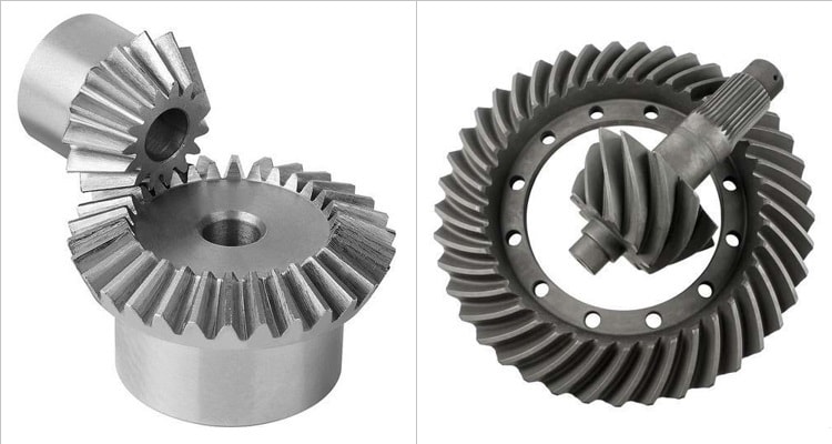
What are the limitations of using spiral gears in certain applications?
While spiral gears offer numerous advantages, they also have certain limitations that need to be considered when selecting them for specific applications. Here are some limitations of using spiral gears:
- Axial Thrust: Spiral gears generate axial thrust due to their helical tooth arrangement. This axial thrust can impose additional forces on the gear shafts and bearings, requiring proper design considerations and potential incorporation of thrust bearings in certain applications. Managing and compensating for axial thrust is crucial to ensure smooth gear operation.
- Manufacturing Complexity: The manufacturing process for spiral gears involves more complexity compared to straight-toothed gears. The helical tooth profile requires specialized cutting tools and machining techniques, adding to the manufacturing cost and complexity. This complexity may limit their use in applications with strict cost constraints or where simplicity of manufacturing is a priority.
- Axial Space Requirement: Spiral gears require more axial space compared to parallel-axis gears. The helical tooth profile results in a longer gear face width, which can limit their use in applications with space constraints. It is important to ensure that sufficient axial space is available to accommodate the larger size of spiral gears.
- Gear Alignment: Proper gear alignment is critical for spiral gears to function optimally. Any misalignment between the driving and driven gears can result in increased noise, vibration, and premature wear. Achieving and maintaining precise gear alignment may require additional attention and care during installation and regular maintenance.
- Speed Limitations: Spiral gears may have certain speed limitations due to the potential for tooth deflection and increased heat generation. At high speeds, the centrifugal forces acting on the helical teeth can cause deflection, leading to reduced gear accuracy and increased noise. Additionally, the sliding contact between the teeth can result in higher heat generation, requiring appropriate lubrication and cooling measures in high-speed applications.
While these limitations exist, they can often be managed or mitigated through proper design, engineering, and maintenance practices. It is important to carefully evaluate the specific requirements and constraints of the application to determine whether spiral gears are suitable or if alternative gear types may be more appropriate.
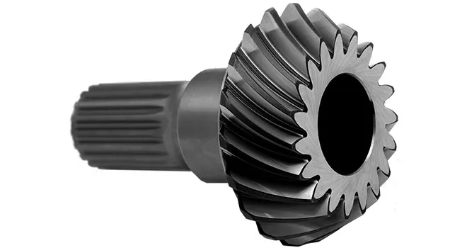
How do spiral gears contribute to smoother and quieter gear engagement?
Spiral gears, also known as helical gears, offer several design features that contribute to smoother and quieter gear engagement compared to other gear types. Here’s how spiral gears achieve this:
- Gradual Tooth Engagement: The helical tooth arrangement in spiral gears allows for gradual tooth engagement as the gears mesh. Unlike straight-cut gears, where the teeth make sudden contact, spiral gears have angled teeth that come into contact gradually. This gradual engagement helps to reduce impact and noise during gear meshing.
- Increased Contact Ratio: The helical tooth design of spiral gears provides a higher contact ratio compared to straight-cut gears. The contact ratio refers to the number of teeth in mesh at any given time. With a higher contact ratio, the load is distributed over multiple teeth, resulting in reduced stress on individual teeth and smoother gear operation.
- Reduced Sliding Friction: The helical tooth arrangement in spiral gears helps minimize sliding friction between the teeth. As the teeth mesh, the angled surfaces slide against each other instead of making direct contact. This sliding action reduces friction and wear, leading to smoother operation and reduced noise levels.
- Efficient Load Distribution: Spiral gears distribute the load over multiple teeth due to their helical tooth arrangement. This distribution of load helps to evenly distribute the forces and minimize localized stresses. By spreading the load, spiral gears can handle higher torque transmission and carry heavier loads, resulting in smoother and more reliable gear engagement.
- Axial Thrust Compensation: Spiral gears can be designed with opposite helix angles on mating gears. This configuration helps cancel out the axial thrust generated during gear meshing. By eliminating or reducing the axial thrust, spiral gears reduce the need for additional thrust bearings and simplify the gear design, contributing to smoother operation.
These design features of spiral gears, including gradual tooth engagement, increased contact ratio, reduced sliding friction, efficient load distribution, and axial thrust compensation, work together to provide smoother and quieter gear engagement. These characteristics make spiral gears ideal for applications where noise reduction, smooth operation, and reliable gear meshing are essential.
editor by CX 2023-10-08
China Standard Drive Axle Spiral Bevel Gear Cone Gear 937h 936 933 Zl30h Wheel Loader Sinomach CZPT worm gear winch
Product Description
| Machine Model: | 937H 936 933 ZL30H Sinomach Xihu (West Lake) Dis.n |
| Model NO: | Z-13E-060-Z0001 |
| Part drawing No: | Z30E.6.2.Z1 |
| Color: | Gray-Black |
| Advantage: | Good Mechanical Properties |
| Toothed Portion Shape: | Spiral Bevel Gear |
| Manufacturing Method: | Forging Gear |
| Deliver Time: | 5 to 7 working days after receiving the advance payment |
Spare parts of Sinomach Xihu (West Lake) Dis.n including:Engine system,Torque Converter and Transmission system,Power train, Hydraulic system,Brake system,Cab and accessorie,Conditioner system,Electrical system,Oil product, etc.
High quality products,enough stock,30 years export experience,we can offer professional service and competitive prices for you .
Sinomach Xihu (West Lake) Dis.n looking CHINAMFG to cooperation with you.
Advantages of Sinomach Xihu (West Lake) Dis.n drive axle:
1. The drive axle housing adopts integral steel castings. The material has excellent mechanical properties, good rigidity and high strength, and can meet the needs of various complex working conditions.
2. The spiral bevel gear is made of alloy structural steel and designed with 35 ° spiral angle, which can bear high load.
3. The brake disc is made of gray cast iron, which has high wear resistance and ensures the ideal friction coefficient.
Parts warehouse
packaging and Shipping
Company Profile
FAQ
1. What is your terms of payment?
T/T 30% as deposit, and balance paid before delivery(We’ll show you the all pictures of the products and packages before paying the balance)
2.How about your delivery time?
Generally, it will take 5 to 7 working days after receiving your advance payment. The specific delivery time depends on the quantity of your order.
3. Do you test all your goods before delivery?
A: Yes, we will have 100% test and double check before delivery.
4. How do you make our business long-term and good relationship?
(1) We keep good quality and competitive price to ensure our customers benefit
(2) We respect every customer as our friend and we sincerely do business and make friends with them, no matter where they come from.
5.After -sales service
We have QC department to guarantee the quality before delivery, If the products have any quality problems, our company will be responsible for it.
6.What kind of package?
Wooden cases, cartons, or the packaging you specify.
| After-sales Service: | 24-Hour Service Support |
|---|---|
| Warranty: | 6 Months |
| Type: | Gear |
| Application: | Construction Machinery |
| Certification: | ISO9001: 2000 |
| Condition: | New |
| Customization: |
Available
| Customized Request |
|---|
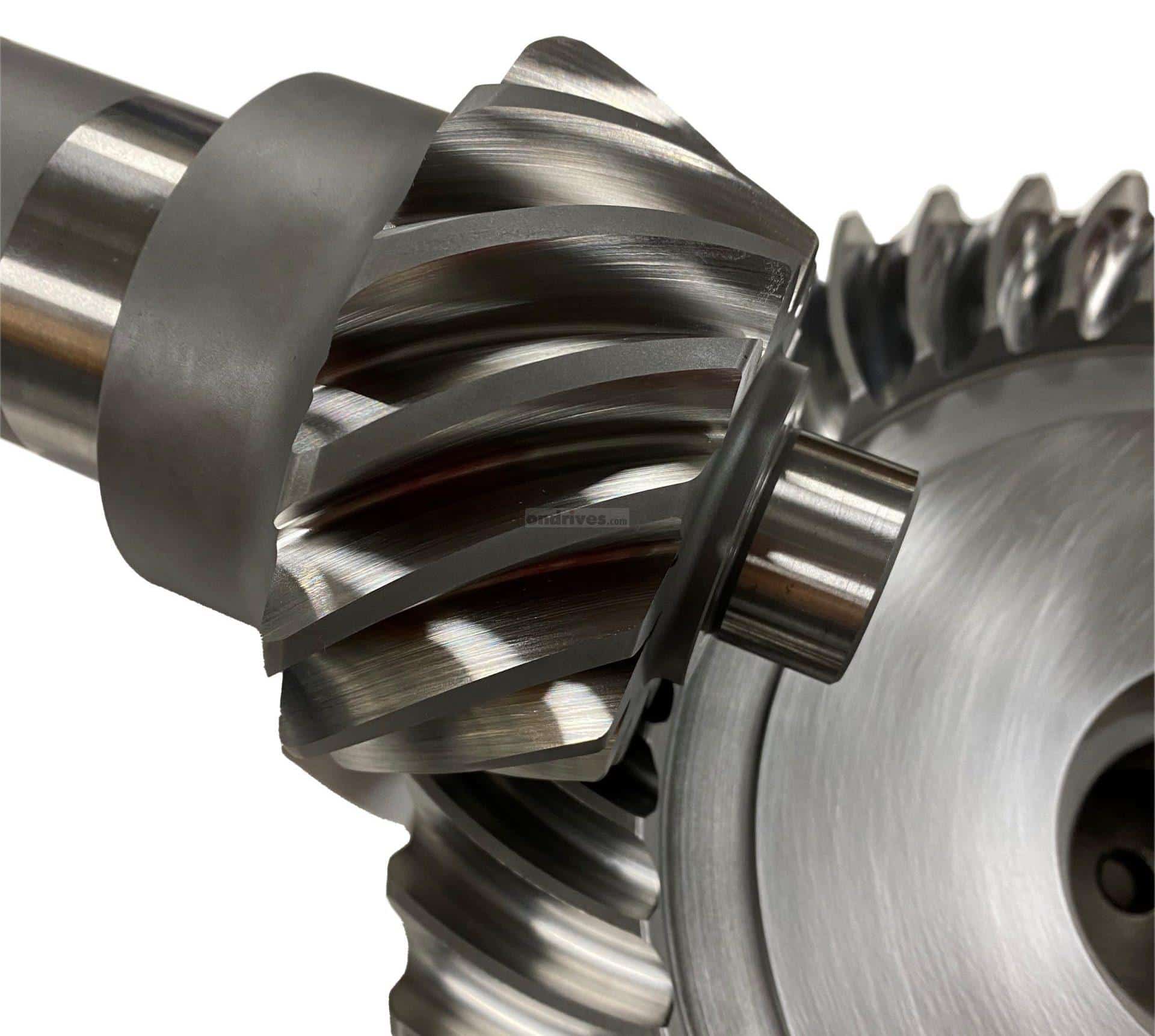
Can spiral gears be used in heavy-duty industrial machinery?
Yes, spiral gears can be effectively used in heavy-duty industrial machinery. They offer several advantages that make them suitable for such applications. Here’s why spiral gears are well-suited for heavy-duty industrial machinery:
- High Load Capacity: Spiral gears have a high load-carrying capacity, allowing them to handle heavy loads encountered in industrial machinery. The helical tooth profile distributes the load across multiple teeth, reducing stress concentration and enhancing overall load-bearing capability.
- Smooth Operation: The helical tooth arrangement of spiral gears ensures smooth and precise gear operation. The gradual tooth engagement minimizes impact and vibrations, resulting in smoother gear meshing and reduced noise levels. This smooth operation is crucial in heavy-duty machinery to ensure reliable performance and minimize wear and tear.
- Efficient Power Transmission: Spiral gears offer efficient power transmission, making them suitable for heavy-duty applications. The helical tooth profile reduces sliding friction, resulting in improved power transmission efficiency and reduced energy losses. This efficiency is particularly important in industrial machinery where high power transmission and energy conservation are critical.
- Durability and Reliability: Spiral gears are known for their durability and reliability. The gradual tooth engagement, load distribution, and reduced sliding friction contribute to their long-term performance under demanding conditions. Heavy-duty industrial machinery requires gears that can withstand continuous use and maintain high reliability, making spiral gears a suitable choice.
- Axial Thrust Compensation: Spiral gears can be designed with opposite helix angles on mating gears to cancel out axial thrust. This axial thrust compensation simplifies gear design and reduces the need for additional components such as thrust bearings. It is particularly advantageous in heavy-duty machinery, where minimizing axial forces and ensuring smooth operation are critical.
Considering their high load capacity, smooth operation, efficient power transmission, durability, and axial thrust compensation, spiral gears are well-suited for heavy-duty industrial machinery. They can handle the demanding requirements and provide reliable performance, making them a preferred choice in many heavy-duty applications.
What are the limitations of using spiral gears in certain applications?
While spiral gears offer numerous advantages, they also have certain limitations that need to be considered when selecting them for specific applications. Here are some limitations of using spiral gears:
- Axial Thrust: Spiral gears generate axial thrust due to their helical tooth arrangement. This axial thrust can impose additional forces on the gear shafts and bearings, requiring proper design considerations and potential incorporation of thrust bearings in certain applications. Managing and compensating for axial thrust is crucial to ensure smooth gear operation.
- Manufacturing Complexity: The manufacturing process for spiral gears involves more complexity compared to straight-toothed gears. The helical tooth profile requires specialized cutting tools and machining techniques, adding to the manufacturing cost and complexity. This complexity may limit their use in applications with strict cost constraints or where simplicity of manufacturing is a priority.
- Axial Space Requirement: Spiral gears require more axial space compared to parallel-axis gears. The helical tooth profile results in a longer gear face width, which can limit their use in applications with space constraints. It is important to ensure that sufficient axial space is available to accommodate the larger size of spiral gears.
- Gear Alignment: Proper gear alignment is critical for spiral gears to function optimally. Any misalignment between the driving and driven gears can result in increased noise, vibration, and premature wear. Achieving and maintaining precise gear alignment may require additional attention and care during installation and regular maintenance.
- Speed Limitations: Spiral gears may have certain speed limitations due to the potential for tooth deflection and increased heat generation. At high speeds, the centrifugal forces acting on the helical teeth can cause deflection, leading to reduced gear accuracy and increased noise. Additionally, the sliding contact between the teeth can result in higher heat generation, requiring appropriate lubrication and cooling measures in high-speed applications.
While these limitations exist, they can often be managed or mitigated through proper design, engineering, and maintenance practices. It is important to carefully evaluate the specific requirements and constraints of the application to determine whether spiral gears are suitable or if alternative gear types may be more appropriate.
How do spiral gears differ from other types of gears?
Spiral gears, also known as helical gears, have distinct differences compared to other types of gears. These differences primarily stem from the helical tooth arrangement in spiral gears. Here’s how spiral gears differ from other gear types:
- Helical Tooth Arrangement: Spiral gears have teeth that are curved in a spiral pattern, forming a helix. This is different from straight-cut gears, which have teeth parallel to the gear axis, or bevel gears, which have teeth on conical surfaces. The helical tooth arrangement in spiral gears provides various advantages such as smoother operation, increased load capacity, and improved efficiency.
- Gradual Tooth Engagement: Due to the helical tooth arrangement, spiral gears have a gradual tooth engagement as the gears rotate. This gradual contact reduces impact and noise during gear meshing, resulting in smoother and quieter operation compared to straight-cut gears.
- Axial Thrust Compensation: Spiral gears can be designed with opposite helix angles on mating gears, which helps in canceling out the axial thrust generated during gear meshing. This feature eliminates the need for additional thrust bearings and simplifies the gear design, reducing complexity.
- Load Distribution: The helical tooth arrangement in spiral gears allows the load to be distributed over multiple teeth. This enables spiral gears to handle higher torque transmission and carry heavier loads compared to straight-cut gears.
- Efficiency: Spiral gears exhibit higher efficiency due to reduced sliding friction between the teeth. The helical tooth arrangement helps minimize sliding friction, resulting in lower power losses during gear operation.
- Versatility: Spiral gears can be manufactured in various configurations, including spur, helical, and double helical designs. This versatility allows for their application in a wide range of machinery and systems, providing flexibility in gear design and usage.
These differences make spiral gears well-suited for applications that require smooth operation, high load capacity, and efficient power transmission. They are commonly used in gearboxes, automotive differentials, machine tools, and various industrial machinery.
In summary, spiral gears stand out from other gear types due to their helical tooth arrangement, resulting in smoother operation, increased load capacity, improved efficiency, and versatility.
editor by CX 2023-10-07
China manufacturer Truck Bus Spiral Bevel CZPT and Pinion worm gear winch
Product Description
Truck Bus Spiral Bevel CHINAMFG And Pinion
| Mechanical Equipment parts Bevel Gears
Bevel gears are useful when the direction of a shaft’s rotation needs to be changed. They are usually mounted on shafts that are 90 degrees apart, but can be designed to work at other angles as well.The teeth on bevel gears can be straight, spiral or hypoid. Straight bevel gear teeth actually have the same problem as straight spur gear teeth — as each tooth engages, it impacts the corresponding tooth all at once |
||
|
High quality gear supplier 1.precise manufacturing processes and strict quality control, our factory can create excellent quality. |
||
|
Tolerance |
0.003mm-0.01mm |
|
|
Surface finish |
Based on customer requirements, we can do Plating(Zinc plated, Nickel plated, Chrome plated,etc), polishing(precision can reach +/-0.005mm), knurling, anodizing, Black Oxide, heat treatment, sandblasting, powder coating, etc. |
|
|
Precision processing |
turning, milling, drilling, grinding, wire-EDM cutting etc |
|
|
Material range |
Metal: Stainless Steel, Brass,Copper, Brozone, Aluminum, Steel, Carbon Steel etc. |
|
|
Plastic : PU, PVC, POM, PMMA, Nylon ,HDPE etc. |
||
|
QC(inspection everywhere)
|
– Technicians self-check in production |
|
|
– Engineer spot check in production. |
||
|
– QC inspect after products finished |
||
|
– International sales who were trained the technical know-how spot check before shipping to ensure the quality. |
||
|
MOQ |
1-100pcs |
|
|
Payment |
30% in advance, 70% before shipment |
|
| Industry application |
Appliance/ Automotive/ Agricultural Electronics/ Industrial/ Marine Mining/ Hydraulics/ Valves Oil and Gas/ Electrical/ Construction |
|
| Model | Gear ratio | Module | No. of teeth | Diraction of spiral | Shape | Bore | Hub dia. | Pitch dia. | Outside Dia. | Mounting distance | Total lemgth | crown to back length |
| AH7 | B | C | D | E | F | G | ||||||
| TBGG2-3571R | 1.5 | m2 | 30 | R | B4 | 12 | 35 | 60 | 61.06 | 40 | 26.60 | 21.20 |
| TBGG2-2030L | 20 | L | B3 | 10 | 30 | 40 | 43.55 | 45 | 24.91 | 16.18 | ||
| TBGG2.5-3571R | m2.5 | 30 | R | B4 | 15 | 45 | 75 | 77.09 | 50 | 33.86 | 26.56 | |
| TBGG2.5-2030L | 20 | L | B3 | 12 | 40 | 50 | 54.43 | 55 | 30.88 | 18.98 | ||
| TBGG3-3571R | m3 | 30 | R | B4 | 16 | 50 | 90 | 92.21 | 50 | 35.34 | 26.66 | |
| TBGG3-2030L | 20 | L | B3 | 16 | 40 | 60 | 65.58 | 70 | 40.17 | 26.86 | ||
| TBGG4-3571R | m4 | 30 | R | B4 | 20 | 70 | 120 | 122.85 | 75 | 47.48 | 37.14 | |
| TBGG4-2030L | 20 | L | B3 | 20 | 60 | 80 | 87.34 | 90 | 48.17 | 32.45 | ||
| TBGG2-4571R | 2 | m2 | 40 | R | B4 | 12 | 40 | 80 | 80.99 | 40 | 32.26 | 25.99 |
| TBGG2-2040L | 20 | L | B3 | 12 | 32 | 40 | 40.10 | 60 | 34.04 | 21.02 | ||
| TBGG2.5-4571R | m2.5 | 40 | R | B4 | 15 | 50 | 100 | 101.27 | 55 | 39.65 | 31.27 | |
| TBGG2.5-2040L | 20 | L | B3 | 12 | 40 | 50 | 55.21 | 75 | 43.61 | 26.30 | ||
| TBGG3-4571R | m3 | 40 | R | B4 | 20 | 60 | 120 | 121.48 | 65 | 45.76 | 36.48 | |
| TBGG3-2040L | 20 | L | B3 | 16 | 50 | 60 | 66.06 | 90 | 50.63 | 31.52 | ||
| TBGG4-4571R | m4 | 40 | R | B4 | 20 | 70 | 160 | 162.07 | 80 | 53.69 | 42.07 | |
| TBGG4-2040L | 20 | L | B3 | 20 | 60 | 80 | 88.55 | 120 | 66.24 | 42.12 | ||
| TBGG2-4515R | 3 | m2 | 45 | R | B4 | 12 | 40 | 90 | 96.67 | 40 | 30.29 | 26.01 |
| TBGG2-1545L | 15 | L | B3 | 10 | 24 | 30 | 34.78 | 60 | 29.66 | 15.80 | ||
| TBGG2.5-4515R | m2.5 | 45 | R | B4 | 15 | 50 | 112.7 | 113.32 | 50 | 28.25 | 32.47 | |
| TBGG2.5-1545L | 15 | L | B3 | 12 | 30 | 37.5 | 43.36 | 75 | 38.27 | 19.73 | ||
| TBGG3-4515R | m3 | 45 | R | B4 | 20 | 60 | 135 | 135.99 | 55 | 40.59 | 33.98 | |
| TBGG3-1545L | 15 | L | B3 | 15 | 38 | 45 | 52.08 | 90 | 44.98 | 23.68 |
HangZhou HUANBALL Professional custom and design precision machined parts. We provide custom complete turnkey precision machining solutions to thousands of customers in diverse markets throughout the world, including medical, automotive, marine, aerospace, defense, precision instrument, home appliance, electronics, machinery, oil & gas, sensors and more.
We offer customized precision machining service and solutions that help customers meet strict operational demands.Serving a CHINAMFG customer base, we do this with:
1*Over 100 full time engineers & workers on staff to optimize efficiency and cost saving
2*Extensive testing to get the sample and mass production right the first time
3*Comprehensive in-house capabilities to meet all customer needs
4*Over 30,000 square CHINAMFG of manufacturing plant
5*Expert design and development for all custom precision machining parts
6*To better control the quality of the customized parts, we’ve invested substantially in equipment, facilities, and training. Our investments enable us to deliver every order according to specification – on time and on budget.
==================================== FAQ ======================================
1) Q: I haven’t done business with you before, how can i trust your company?
A: Our company are made-in-china CHINAMFG supplier and passed Field certification by made-in-china. What’s more,we’ve got authority certificates for ISO9001.
2) Q: How is quality ensured?
A: All our processes strictly adhere to ISO9001:2008 procedures, we have strict quality control from producing to delivery,100% inspection by professional testing centre. Small samples could be provided to you for testing.
3) Q: Can i get 1 or more samples?
A: Yes, sample orders welcomed.
4) Q: Do you give any discounts?
A: Yes, we’ll surely try my best to help you get the best price and best service at the same time.
5) Q: How to Custom-made(OEM/ODM)?
A: Please send you product drawings or samples to us if you have, and we can custom-made as you requirements.We will also provide professional advices of the products to make the design to be maximize the performance.
| Application: | Motor, Electric Cars, Motorcycle, Machinery, Marine, Toy, Agricultural Machinery, Car, Printing Machine,Cooling Tower,Power Plant |
|---|---|
| Hardness: | Hardened Tooth Surface |
| Gear Position: | Bevel Gear |
| Manufacturing Method: | Cut Gear |
| Toothed Portion Shape: | Bevel Gear |
| Material: | Stainless Steel, Brass,Copper, Brozone, Aluminum, |
| Samples: |
US$ 50/Piece
1 Piece(Min.Order) | |
|---|
| Customization: |
Available
| Customized Request |
|---|
How do spiral gears contribute to reducing noise and vibration?
Spiral gears contribute significantly to reducing noise and vibration in gear systems. Their unique design and characteristics help minimize unwanted sound and vibrations. Here’s how spiral gears achieve noise and vibration reduction:
- Gradual Tooth Engagement: Spiral gears have a helical tooth arrangement, which results in gradual tooth engagement as the gears mesh. Unlike spur gears with instantaneous full tooth contact, the helical teeth of spiral gears gradually come into contact, reducing the impact and shock during gear meshing. This gradual engagement helps to minimize noise and vibration.
- Improved Contact Pattern: The helical tooth profile of spiral gears produces a favorable contact pattern between the teeth. The contact pattern is more evenly distributed across the tooth face compared to spur gears, which reduces stress concentration and potential noise generation. The improved contact pattern contributes to smoother and quieter gear operation.
- Load Distribution: Spiral gears distribute the load over multiple teeth due to their helical shape. This load distribution helps to minimize localized stresses and reduces the risk of tooth breakage or pitting, which can contribute to noise and vibration. By spreading the load across a larger contact area, spiral gears ensure smoother and more stable gear operation.
- Reduced Sliding Friction: The sliding friction between gear teeth can generate noise and vibration. Spiral gears, with their helical tooth profile, exhibit reduced sliding friction compared to spur gears. The sliding motion is distributed along the helical path, resulting in smoother tooth contact and reduced friction-induced noise and vibration.
Collectively, these factors—gradual tooth engagement, improved contact pattern, load distribution, and reduced sliding friction—contribute to the noise and vibration reduction achieved by spiral gears. This makes them particularly suitable for applications where quiet operation and minimal vibration are essential, such as precision machinery, automotive transmissions, and other noise-sensitive environments.
How do you calculate the gear ratio in a spiral gear system?
The gear ratio in a spiral gear system can be calculated by comparing the number of teeth on the driving gear (pinion) to the number of teeth on the driven gear (gear). The gear ratio represents the ratio of the angular velocity (speed) of the driving gear to the angular velocity of the driven gear. Here’s the formula to calculate the gear ratio:
Gear Ratio = Number of Teeth on Driven Gear / Number of Teeth on Driving Gear
For example, consider a spiral gear system where the driving gear (pinion) has 20 teeth, and the driven gear (gear) has 40 teeth. The gear ratio can be calculated as follows:
Gear Ratio = 40 / 20 = 2
In this example, the gear ratio is 2, which means the driven gear will rotate at half the speed of the driving gear. This calculation assumes that the gears have the same module (gear size) and that there are no additional gear stages in the system.
It’s important to note that the gear ratio determines the speed and torque relationship between the driving and driven gears. A gear ratio greater than 1 (e.g., 2, 3, etc.) indicates a reduction in speed and an increase in torque, while a gear ratio less than 1 (e.g., 0.5, 0.75, etc.) indicates an increase in speed and a reduction in torque.
When working with spiral gears, it’s essential to consider the helix angle and axial thrust in addition to the gear ratio to ensure proper gear design and performance.
Can you explain the advantages of using spiral gears over other gear types?
Spiral gears, also known as helical gears, offer several advantages over other gear types. These advantages stem from their unique design and characteristics. Here are some key advantages of using spiral gears:
- Smooth and Quiet Operation: The helical tooth arrangement in spiral gears enables gradual tooth engagement, resulting in smoother and quieter operation compared to straight-cut gears. The angled teeth allow for gradual contact, reducing impact and noise during gear meshing.
- High Load Capacity: Spiral gears can handle higher loads compared to straight-cut gears. The helical tooth design distributes the load over multiple teeth, increasing the load-carrying capacity and providing improved strength. This makes spiral gears well-suited for applications that require the transmission of high torque or the handling of significant loads.
- Efficient Power Transmission: Spiral gears exhibit higher efficiency compared to straight-cut gears. The helical tooth arrangement helps minimize sliding friction between the teeth, resulting in reduced power losses due to friction during gear operation. This efficiency is crucial in applications where power transmission needs to be optimized, and energy losses need to be minimized.
- Reduced Noise and Vibration: The gradual tooth engagement in spiral gears leads to reduced impact and vibration during gear meshing. This results in quieter operation, making spiral gears suitable for applications where noise reduction is important, such as in precision machinery or noise-sensitive environments.
- Axial Thrust Compensation: Spiral gears can be designed with opposite helix angles on mating gears, which helps cancel out the axial thrust generated during gear meshing. This feature eliminates the need for additional thrust bearings, simplifying the gear design and reducing complexity.
- Versatility and Adaptability: Spiral gears can be manufactured in various configurations, including spur, helical, and double helical designs. This versatility allows for their application in a wide range of machinery and systems, providing flexibility in gear design and usage.
These advantages make spiral gears a preferred choice in many applications where smooth operation, high load capacity, efficient power transmission, reduced noise, and versatility are important considerations.
editor by CX 2023-09-28
China Custom Truck Bus Spiral Bevel CZPT and Pinion gear ratio calculator
Product Description
Truck Bus Spiral Bevel CHINAMFG And Pinion
| Mechanical Equipment parts Bevel Gears
Bevel gears are useful when the direction of a shaft’s rotation needs to be changed. They are usually mounted on shafts that are 90 degrees apart, but can be designed to work at other angles as well.The teeth on bevel gears can be straight, spiral or hypoid. Straight bevel gear teeth actually have the same problem as straight spur gear teeth — as each tooth engages, it impacts the corresponding tooth all at once |
||
|
High quality gear supplier 1.precise manufacturing processes and strict quality control, our factory can create excellent quality. |
||
|
Tolerance |
0.003mm-0.01mm |
|
|
Surface finish |
Based on customer requirements, we can do Plating(Zinc plated, Nickel plated, Chrome plated,etc), polishing(precision can reach +/-0.005mm), knurling, anodizing, Black Oxide, heat treatment, sandblasting, powder coating, etc. |
|
|
Precision processing |
turning, milling, drilling, grinding, wire-EDM cutting etc |
|
|
Material range |
Metal: Stainless Steel, Brass,Copper, Brozone, Aluminum, Steel, Carbon Steel etc. |
|
|
Plastic : PU, PVC, POM, PMMA, Nylon ,HDPE etc. |
||
|
QC(inspection everywhere)
|
– Technicians self-check in production |
|
|
– Engineer spot check in production. |
||
|
– QC inspect after products finished |
||
|
– International sales who were trained the technical know-how spot check before shipping to ensure the quality. |
||
|
MOQ |
1-100pcs |
|
|
Payment |
30% in advance, 70% before shipment |
|
| Industry application |
Appliance/ Automotive/ Agricultural Electronics/ Industrial/ Marine Mining/ Hydraulics/ Valves Oil and Gas/ Electrical/ Construction |
|
| Model | Gear ratio | Module | No. of teeth | Diraction of spiral | Shape | Bore | Hub dia. | Pitch dia. | Outside Dia. | Mounting distance | Total lemgth | crown to back length |
| AH7 | B | C | D | E | F | G | ||||||
| TBGG2-3571R | 1.5 | m2 | 30 | R | B4 | 12 | 35 | 60 | 61.06 | 40 | 26.60 | 21.20 |
| TBGG2-2030L | 20 | L | B3 | 10 | 30 | 40 | 43.55 | 45 | 24.91 | 16.18 | ||
| TBGG2.5-3571R | m2.5 | 30 | R | B4 | 15 | 45 | 75 | 77.09 | 50 | 33.86 | 26.56 | |
| TBGG2.5-2030L | 20 | L | B3 | 12 | 40 | 50 | 54.43 | 55 | 30.88 | 18.98 | ||
| TBGG3-3571R | m3 | 30 | R | B4 | 16 | 50 | 90 | 92.21 | 50 | 35.34 | 26.66 | |
| TBGG3-2030L | 20 | L | B3 | 16 | 40 | 60 | 65.58 | 70 | 40.17 | 26.86 | ||
| TBGG4-3571R | m4 | 30 | R | B4 | 20 | 70 | 120 | 122.85 | 75 | 47.48 | 37.14 | |
| TBGG4-2030L | 20 | L | B3 | 20 | 60 | 80 | 87.34 | 90 | 48.17 | 32.45 | ||
| TBGG2-4571R | 2 | m2 | 40 | R | B4 | 12 | 40 | 80 | 80.99 | 40 | 32.26 | 25.99 |
| TBGG2-2040L | 20 | L | B3 | 12 | 32 | 40 | 40.10 | 60 | 34.04 | 21.02 | ||
| TBGG2.5-4571R | m2.5 | 40 | R | B4 | 15 | 50 | 100 | 101.27 | 55 | 39.65 | 31.27 | |
| TBGG2.5-2040L | 20 | L | B3 | 12 | 40 | 50 | 55.21 | 75 | 43.61 | 26.30 | ||
| TBGG3-4571R | m3 | 40 | R | B4 | 20 | 60 | 120 | 121.48 | 65 | 45.76 | 36.48 | |
| TBGG3-2040L | 20 | L | B3 | 16 | 50 | 60 | 66.06 | 90 | 50.63 | 31.52 | ||
| TBGG4-4571R | m4 | 40 | R | B4 | 20 | 70 | 160 | 162.07 | 80 | 53.69 | 42.07 | |
| TBGG4-2040L | 20 | L | B3 | 20 | 60 | 80 | 88.55 | 120 | 66.24 | 42.12 | ||
| TBGG2-4515R | 3 | m2 | 45 | R | B4 | 12 | 40 | 90 | 96.67 | 40 | 30.29 | 26.01 |
| TBGG2-1545L | 15 | L | B3 | 10 | 24 | 30 | 34.78 | 60 | 29.66 | 15.80 | ||
| TBGG2.5-4515R | m2.5 | 45 | R | B4 | 15 | 50 | 112.7 | 113.32 | 50 | 28.25 | 32.47 | |
| TBGG2.5-1545L | 15 | L | B3 | 12 | 30 | 37.5 | 43.36 | 75 | 38.27 | 19.73 | ||
| TBGG3-4515R | m3 | 45 | R | B4 | 20 | 60 | 135 | 135.99 | 55 | 40.59 | 33.98 | |
| TBGG3-1545L | 15 | L | B3 | 15 | 38 | 45 | 52.08 | 90 | 44.98 | 23.68 |
HangZhou HUANBALL Professional custom and design precision machined parts. We provide custom complete turnkey precision machining solutions to thousands of customers in diverse markets throughout the world, including medical, automotive, marine, aerospace, defense, precision instrument, home appliance, electronics, machinery, oil & gas, sensors and more.
We offer customized precision machining service and solutions that help customers meet strict operational demands.Serving a CHINAMFG customer base, we do this with:
1*Over 100 full time engineers & workers on staff to optimize efficiency and cost saving
2*Extensive testing to get the sample and mass production right the first time
3*Comprehensive in-house capabilities to meet all customer needs
4*Over 30,000 square CHINAMFG of manufacturing plant
5*Expert design and development for all custom precision machining parts
6*To better control the quality of the customized parts, we’ve invested substantially in equipment, facilities, and training. Our investments enable us to deliver every order according to specification – on time and on budget.
==================================== FAQ ======================================
1) Q: I haven’t done business with you before, how can i trust your company?
A: Our company are made-in-china CHINAMFG supplier and passed Field certification by made-in-china. What’s more,we’ve got authority certificates for ISO9001.
2) Q: How is quality ensured?
A: All our processes strictly adhere to ISO9001:2008 procedures, we have strict quality control from producing to delivery,100% inspection by professional testing centre. Small samples could be provided to you for testing.
3) Q: Can i get 1 or more samples?
A: Yes, sample orders welcomed.
4) Q: Do you give any discounts?
A: Yes, we’ll surely try my best to help you get the best price and best service at the same time.
5) Q: How to Custom-made(OEM/ODM)?
A: Please send you product drawings or samples to us if you have, and we can custom-made as you requirements.We will also provide professional advices of the products to make the design to be maximize the performance.
| Application: | Motor, Electric Cars, Motorcycle, Machinery, Marine, Toy, Agricultural Machinery, Car, Printing Machine,Cooling Tower,Power Plant |
|---|---|
| Hardness: | Hardened Tooth Surface |
| Gear Position: | Bevel Gear |
| Manufacturing Method: | Cut Gear |
| Toothed Portion Shape: | Bevel Gear |
| Material: | Stainless Steel, Brass,Copper, Brozone, Aluminum, |
| Samples: |
US$ 50/Piece
1 Piece(Min.Order) | |
|---|
| Customization: |
Available
| Customized Request |
|---|
How do spiral gears handle variations in tooth engagement during operation?
Spiral gears are designed to handle variations in tooth engagement during operation effectively. The unique helical tooth arrangement of spiral gears allows them to accommodate these variations and provide several benefits. Here’s how spiral gears handle variations in tooth engagement:
- Gradual Engagement: One of the key advantages of spiral gears is their ability to achieve gradual tooth engagement. As the gears rotate, the helical shape of the teeth allows them to come into contact gradually, starting from one end of the gear to the other. This gradual engagement minimizes the impact and shock that would occur with sudden full tooth contact in other gear types. It results in smoother and quieter operation, reducing noise, vibrations, and stress on the gear system.
- Increased Tooth Contact Area: Spiral gears provide a larger tooth contact area compared to straight-cut or spur gears. The helical tooth profile extends the contact length along the gear face, distributing the load over multiple teeth at any given moment. This increased contact area enables spiral gears to handle higher loads and transmit torque more efficiently.
- Load Sharing: Due to the helical arrangement, spiral gears naturally distribute the load across multiple teeth. This load-sharing characteristic helps to minimize tooth wear and fatigue. As the gears rotate, different teeth come into contact, ensuring that the load is distributed evenly. This load sharing capability enhances the gear system’s durability and extends its service life, particularly in applications with fluctuating loads.
- Reduction of Side Thrust: Spiral gears generate an axial thrust force during operation. However, by using pairs of spiral gears with opposite helix angles, this side thrust force can be greatly reduced or even eliminated. When paired gears with opposite helix angles mesh together, the axial thrust forces cancel each other out. This eliminates the need for additional thrust bearings or complex gear arrangements to counteract the axial forces, simplifying the gear system design.
- Improved Lubrication: The helical tooth profile of spiral gears promotes better lubrication. The continuous sliding motion between the teeth creates a pumping action that helps distribute lubricant along the tooth surfaces. This improved lubrication reduces friction, heat generation, and wear, enhancing the overall efficiency and longevity of the gear system.
These features of spiral gears—gradual engagement, increased tooth contact area, load sharing, reduction of side thrust, and improved lubrication—make them highly effective in handling variations in tooth engagement during operation. Spiral gears are commonly used in various applications such as automotive transmissions, industrial machinery, and power generation systems, where smooth and reliable power transmission is crucial.
What are the benefits of using spiral gears in high-torque applications?
Spiral gears, also known as helical gears, offer several benefits when used in high-torque applications. These advantages make them well-suited for transmitting large amounts of torque efficiently and reliably. Here are the key benefits of using spiral gears in high-torque applications:
- High Load Capacity: Spiral gears are designed to handle high loads and transmit significant amounts of torque. The helical tooth arrangement allows for load distribution across multiple teeth, reducing stress concentration on individual teeth. This design feature enables spiral gears to withstand the heavy forces encountered in high-torque applications.
- Smooth and Efficient Power Transmission: The helical shape of the teeth in spiral gears enables smooth and continuous contact between the mating gears. This gradual tooth engagement results in reduced impact and vibration during gear meshing. Additionally, the helical tooth profile minimizes sliding friction, leading to efficient power transmission and reduced energy losses, which is particularly important in high-torque applications where power efficiency is crucial.
- Reduced Noise and Vibration: The gradual tooth engagement and improved contact pattern in spiral gears contribute to reduced noise and vibration during operation. The helical tooth arrangement helps to distribute the load more evenly, minimizing dynamic forces and resulting in quieter gear operation. This is especially beneficial in high-torque applications where noise reduction is desired, such as precision machinery or noise-sensitive environments.
- Axial Thrust Compensation: Spiral gears can be designed with opposite helix angles on mating gears, which helps cancel out the axial thrust generated during gear meshing. This feature is particularly advantageous in high-torque applications where managing axial forces is critical. By eliminating or reducing the axial thrust, spiral gears simplify the gear design and reduce the need for additional components, such as thrust bearings.
- Reliability and Durability: The robust design of spiral gears, combined with their ability to handle high loads and transmit torque efficiently, contributes to their overall reliability and durability in high-torque applications. The gradual tooth engagement, load distribution, and reduced friction help minimize wear and extend the service life of the gears, ensuring long-term performance under demanding conditions.
These benefits make spiral gears an excellent choice for high-torque applications where reliable and efficient power transmission, smooth operation, reduced noise, and durability are essential requirements.
How do spiral gears contribute to smoother and quieter gear engagement?
Spiral gears, also known as helical gears, offer several design features that contribute to smoother and quieter gear engagement compared to other gear types. Here’s how spiral gears achieve this:
- Gradual Tooth Engagement: The helical tooth arrangement in spiral gears allows for gradual tooth engagement as the gears mesh. Unlike straight-cut gears, where the teeth make sudden contact, spiral gears have angled teeth that come into contact gradually. This gradual engagement helps to reduce impact and noise during gear meshing.
- Increased Contact Ratio: The helical tooth design of spiral gears provides a higher contact ratio compared to straight-cut gears. The contact ratio refers to the number of teeth in mesh at any given time. With a higher contact ratio, the load is distributed over multiple teeth, resulting in reduced stress on individual teeth and smoother gear operation.
- Reduced Sliding Friction: The helical tooth arrangement in spiral gears helps minimize sliding friction between the teeth. As the teeth mesh, the angled surfaces slide against each other instead of making direct contact. This sliding action reduces friction and wear, leading to smoother operation and reduced noise levels.
- Efficient Load Distribution: Spiral gears distribute the load over multiple teeth due to their helical tooth arrangement. This distribution of load helps to evenly distribute the forces and minimize localized stresses. By spreading the load, spiral gears can handle higher torque transmission and carry heavier loads, resulting in smoother and more reliable gear engagement.
- Axial Thrust Compensation: Spiral gears can be designed with opposite helix angles on mating gears. This configuration helps cancel out the axial thrust generated during gear meshing. By eliminating or reducing the axial thrust, spiral gears reduce the need for additional thrust bearings and simplify the gear design, contributing to smoother operation.
These design features of spiral gears, including gradual tooth engagement, increased contact ratio, reduced sliding friction, efficient load distribution, and axial thrust compensation, work together to provide smoother and quieter gear engagement. These characteristics make spiral gears ideal for applications where noise reduction, smooth operation, and reliable gear meshing are essential.
editor by CX 2023-09-28
China Best Sales F Series Parallel Axis Helical Gear Reducer Vertical Equipment Spiral Machine Gear Reducer Shangyu Gear bevel spiral gear
Product Description
Gearbox Description
Standard Gearboxes Best price Parallel Shaft F series parallel bevel gear speed reducer
Features:
1. Modular design, compact structure. Extra-slim parallel shaft helical gearmotors are the perfect solution when space is limited
2. F series parallel shaft helical gearmotors are typically used in conveyors and materials processing applications
3. Multi-stage(2 or 3 stages) gear units for low output speed
4. Hollow output shaft with keyed connection, shrink disk, splined hollow shaft, or torque arm
5. Can be combined with other types of gearboxes (Such as R Series, UDL Series)
6. Optional mounting options (foot-mounted, flange-mounted, shaft-mounted)
Gearbox Application
|
F Series Gearbox Reducer |
|
|
Product name |
F series of the gearbox hollow shaft model F107 oil seal transmission gearbox reducer reduction |
|
Warranty |
1 years |
|
Applicable Industries |
Manufacturing Plant |
|
Weight (KG) |
50KG |
|
Customized support |
OEM |
|
Gearing Arrangement |
Helical |
|
Output Torque |
1.8-2430N.M |
|
Input Speed |
1440, 2800,960,750 |
|
Output Speed |
0.5 to 200 |
|
Place of Origin |
China |
|
Product name |
F Series Parallel Shaft Gearbox Reducer |
|
Application |
Hardened Tooth Surface |
|
Installation |
Horizontal Type |
|
Layout |
Coaxial |
|
Gear Shape |
Helical |
|
Production Capacity |
800-1500PCS /Month |
|
Type |
Gear Reduction Motor |
|
Color |
Blue,Sliver or Customized |
|
Packing |
Wooden Box |
Detailed Photos
–Modular design, wide transmission ratio coverage, fine and reasonable distribution; Force reducer
–There are 11 types of frame specifications from F.27-F.157, and the transmission power range is 0.12KW-200KW;
–The shape design is suitable for omnidirectional universal installation configuration;
–The transmission is relatively accurate, covering the range of 3.77-281.71, and can be selected as required;
–The gear is grinded by high-precision gear grinding machine, with balanced transmission, low noise, and interstage efficiency of 98%;
–The transmission ratio of the F.R.reducer is extended to 31431, which is specially designed for special low-speed occasions
Editing and broadcasting of main materials
–Box: cast iron;
–Gear: low carbon alloy steel, carbonitriding treatment (after fine grinding, keep the tooth surface hardness of 60HRC, hard layer thickness>0.5mm);
–Flat key: 45 steel, with surface hardness above 45HRC.
Surface painting:
–Cast iron: sprayed with RAL7031 grey blue paint.
Parameter editing broadcast
Power: 0.18KW~200KW
Torque: 3N · m ~ 22500N · m
F series parallel shaft reducer
F series parallel shaft reducer
Output speed: 0.06~374r/minF series parallel shaft reducer [1]
| Application: | Packing Machine, Food Process, Lift, Crane, Agitat |
|---|---|
| Hardness: | Hardened Tooth Surface |
| Installation: | Horizontal Type |
| Layout: | Parallel |
| Gear Shape: | Bevel Gear |
| Step: | Single-Step |
| Samples: |
US$ 500/Piece
1 Piece(Min.Order) | |
|---|
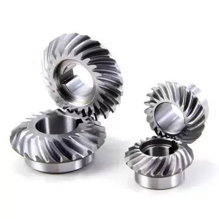
What lubrication and maintenance practices are required for spiral gears?
Spiral gears require proper lubrication and maintenance to ensure optimal performance and longevity. Here are the recommended lubrication and maintenance practices for spiral gears:
- Lubrication: Adequate lubrication is essential for smooth gear operation and to minimize wear. The lubricant forms a protective film between the gear teeth, reducing friction and preventing metal-to-metal contact. It is crucial to use a lubricant that is compatible with the gear material, operating conditions, and load requirements. Regular lubrication intervals should be followed, and the lubricant should be replenished as needed.
- Lubricant Selection: The selection of the lubricant depends on various factors such as gear speed, load, temperature, and environment. It is recommended to consult the gear manufacturer or lubrication experts to determine the most suitable lubricant for the specific application. The lubricant should have appropriate viscosity, additives, and temperature resistance to provide effective lubrication and protect against wear and corrosion.
- Lubricant Application: The lubricant should be applied evenly to the gear teeth and mating surfaces. Depending on the gear design and accessibility, lubrication can be done through oil bath immersion, oil splash, forced circulation, or grease application. It is important to follow the gear manufacturer’s guidelines or industry best practices for proper lubricant application.
- Monitoring and Inspection: Regular monitoring and inspection of the gear condition are essential for early detection of any abnormalities or signs of wear. This can include visual inspections, checking for unusual noise or vibrations, and measuring gear backlash and tooth wear. Monitoring can help identify potential issues and allow for timely maintenance or lubricant adjustments before significant damage occurs.
- Cleaning and Contaminant Control: Regular cleaning of the gears and their surrounding areas is necessary to remove dirt, debris, and contaminants that can affect gear performance and lubrication. Contaminants can accelerate wear and cause damage to the gear teeth. Proper sealing and contamination control measures should be implemented to minimize the ingress of contaminants into the gear system.
- Maintenance Schedule: Establishing a maintenance schedule is important to ensure timely lubricant replenishment, gear inspections, and necessary repairs or replacements. The maintenance schedule should consider the operating conditions, gear load, and manufacturer’s recommendations. Adhering to a well-planned maintenance schedule helps prolong the service life of spiral gears and ensures their continued performance.
By following these lubrication and maintenance practices, spiral gears can maintain their efficiency, durability, and reliability over time. Regular attention to lubrication, monitoring, and maintenance contributes to the smooth operation and extended lifespan of spiral gears in various applications.
What is the impact of helix angle on spiral gear performance?
The helix angle plays a crucial role in determining the performance characteristics of spiral gears. It affects various aspects of gear operation and functionality. Here’s the impact of the helix angle on spiral gear performance:
- Load-Carrying Capacity: The helix angle influences the load-carrying capacity of spiral gears. A larger helix angle results in a more pronounced helical shape of the teeth, providing a larger contact area between the gears. This increased contact area allows spiral gears to distribute the load over more teeth, thereby increasing their load-carrying capacity. Gears with larger helix angles can handle higher loads and transmit more torque.
- Smoothness of Operation: The helix angle significantly affects the smoothness of gear operation. A larger helix angle leads to a more gradual tooth engagement as the gears mesh. This gradual engagement reduces impact and vibration during gear meshing, resulting in smoother operation and reduced noise levels. Spiral gears with larger helix angles are known for their quiet operation and enhanced gear meshing characteristics.
- Efficiency and Power Transmission: The helix angle also influences the efficiency of power transmission in spiral gears. A larger helix angle reduces sliding friction between the teeth during meshing. This reduction in friction results in improved power transmission efficiency and reduced energy losses. Gears with larger helix angles are more efficient in transmitting power, making them suitable for applications where power efficiency is a critical factor.
- Axial Thrust and Thrust Load: The helix angle affects the axial thrust and thrust load in spiral gears. Axial thrust is the force generated in the axial direction due to the helical tooth arrangement. A larger helix angle produces a higher axial thrust, while a smaller angle generates a lower axial thrust. The axial thrust must be considered and managed in gear design to ensure proper gear support and minimize the need for additional thrust bearings.
- Contact Pattern and Gear Meshing: The helix angle influences the contact pattern between the teeth during gear meshing. A larger helix angle shifts the contact pattern across the tooth face, allowing for more even distribution of the load and reduced stress concentration. The contact pattern also affects the gear meshing characteristics, such as tooth wear and noise generation. Proper selection of the helix angle ensures optimal contact pattern and improved gear meshing performance.
The choice of helix angle in spiral gears depends on the specific application requirements, including load capacity, smoothness of operation, power transmission efficiency, and axial thrust considerations. By selecting an appropriate helix angle, engineers can optimize spiral gear performance for different applications, ensuring reliable and efficient gear operation.
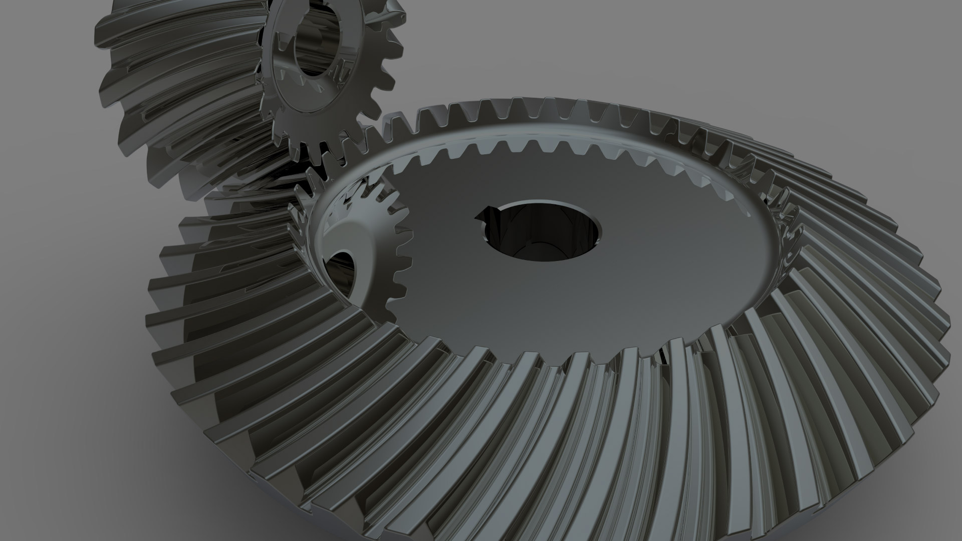
What industries commonly use spiral gears in their applications?
Spiral gears, also known as helical gears, find applications in various industries due to their unique design and advantages. Here are some industries that commonly use spiral gears:
- Automotive: Spiral gears are widely used in the automotive industry, particularly in applications such as gearboxes and automotive differentials. They provide efficient power transmission, smooth operation, and the ability to handle high torque loads.
- Industrial Machinery: Many industrial machinery applications benefit from the use of spiral gears. These include heavy-duty machinery such as mining equipment, construction machinery, and manufacturing machinery. Spiral gears provide high load capacity, efficient power transmission, and reduced noise levels.
- Power Generation: Spiral gears are utilized in power generation systems such as wind turbines, hydroelectric turbines, and steam turbines. They play a critical role in transmitting power from the turbine to the generator, providing efficient and reliable power transmission in these energy production systems.
- Aerospace and Defense: The aerospace and defense industries employ spiral gears in various applications, including aircraft engines, missile systems, and satellite mechanisms. Spiral gears offer high load capacity, efficient power transmission, and the ability to withstand demanding operating conditions.
- Machine Tools: Spiral gears are commonly used in machine tools, such as milling machines, lathes, and grinding machines. These gears contribute to the smooth and precise motion of the tools, ensuring accurate machining operations.
- Robotics and Automation: Spiral gears are utilized in robotics and automation systems for their ability to provide precise and efficient motion transmission. They are crucial components in robotic arms, automated assembly lines, and other industrial automation applications.
These are just a few examples of industries that commonly use spiral gears. However, spiral gears can be found in various other applications where the advantages of smooth operation, high load capacity, efficient power transmission, and reduced noise levels are desired.
editor by CX 2023-09-15
China Custom Custom Farm Machinery Grinding Spiral Bevel Gear raw gear
Product Description
Custom Farm Machinery Grinding Spiral Bevel Gear
| Mechanical Equipment parts Bevel Gears
Bevel gears are useful when the direction of a shaft’s rotation needs to be changed. They are usually mounted on shafts that are 90 degrees apart, but can be designed to work at other angles as well.The teeth on bevel gears can be straight, spiral or hypoid. Straight bevel gear teeth actually have the same problem as straight spur gear teeth — as each tooth engages, it impacts the corresponding tooth all at once |
||
|
High quality gear supplier 1.precise manufacturing processes and strict quality control, our factory can create excellent quality. |
||
|
Tolerance |
0.003mm-0.01mm |
|
|
Surface finish |
Based on customer requirements, we can do Plating(Zinc plated, Nickel plated, Chrome plated,etc), polishing(precision can reach +/-0.005mm), knurling, anodizing, Black Oxide, heat treatment, sandblasting, powder coating, etc. |
|
|
Precision processing |
turning, milling, drilling, grinding, wire-EDM cutting etc |
|
|
Material range |
Metal: Stainless Steel, Brass,Copper, Brozone, Aluminum, Steel, Carbon Steel etc. |
|
|
Plastic : PU, PVC, POM, PMMA, Nylon ,HDPE etc. |
||
|
QC(inspection everywhere)
|
– Technicians self-check in production |
|
|
– Engineer spot check in production. |
||
|
– QC inspect after products finished |
||
|
– International sales who were trained the technical know-how spot check before shipping to ensure the quality. |
||
|
MOQ |
1-100pcs |
|
|
Payment |
30% in advance, 70% before shipment |
|
| Industry application |
Appliance/ Automotive/ Agricultural Electronics/ Industrial/ Marine Mining/ Hydraulics/ Valves Oil and Gas/ Electrical/ Construction |
|
| Model | Gear ratio | Module | No. of teeth | Diraction of spiral | Shape | Bore | Hub dia. | Pitch dia. | Outside Dia. | Mounting distance | Total lemgth | crown to back length |
| AH7 | B | C | D | E | F | G | ||||||
| TBGG2-3571R | 1.5 | m2 | 30 | R | B4 | 12 | 35 | 60 | 61.06 | 40 | 26.60 | 21.20 |
| TBGG2-2030L | 20 | L | B3 | 10 | 30 | 40 | 43.55 | 45 | 24.91 | 16.18 | ||
| TBGG2.5-3571R | m2.5 | 30 | R | B4 | 15 | 45 | 75 | 77.09 | 50 | 33.86 | 26.56 | |
| TBGG2.5-2030L | 20 | L | B3 | 12 | 40 | 50 | 54.43 | 55 | 30.88 | 18.98 | ||
| TBGG3-3571R | m3 | 30 | R | B4 | 16 | 50 | 90 | 92.21 | 50 | 35.34 | 26.66 | |
| TBGG3-2030L | 20 | L | B3 | 16 | 40 | 60 | 65.58 | 70 | 40.17 | 26.86 | ||
| TBGG4-3571R | m4 | 30 | R | B4 | 20 | 70 | 120 | 122.85 | 75 | 47.48 | 37.14 | |
| TBGG4-2030L | 20 | L | B3 | 20 | 60 | 80 | 87.34 | 90 | 48.17 | 32.45 | ||
| TBGG2-4571R | 2 | m2 | 40 | R | B4 | 12 | 40 | 80 | 80.99 | 40 | 32.26 | 25.99 |
| TBGG2-2040L | 20 | L | B3 | 12 | 32 | 40 | 40.10 | 60 | 34.04 | 21.02 | ||
| TBGG2.5-4571R | m2.5 | 40 | R | B4 | 15 | 50 | 100 | 101.27 | 55 | 39.65 | 31.27 | |
| TBGG2.5-2040L | 20 | L | B3 | 12 | 40 | 50 | 55.21 | 75 | 43.61 | 26.30 | ||
| TBGG3-4571R | m3 | 40 | R | B4 | 20 | 60 | 120 | 121.48 | 65 | 45.76 | 36.48 | |
| TBGG3-2040L | 20 | L | B3 | 16 | 50 | 60 | 66.06 | 90 | 50.63 | 31.52 | ||
| TBGG4-4571R | m4 | 40 | R | B4 | 20 | 70 | 160 | 162.07 | 80 | 53.69 | 42.07 | |
| TBGG4-2040L | 20 | L | B3 | 20 | 60 | 80 | 88.55 | 120 | 66.24 | 42.12 | ||
| TBGG2-4515R | 3 | m2 | 45 | R | B4 | 12 | 40 | 90 | 96.67 | 40 | 30.29 | 26.01 |
| TBGG2-1545L | 15 | L | B3 | 10 | 24 | 30 | 34.78 | 60 | 29.66 | 15.80 | ||
| TBGG2.5-4515R | m2.5 | 45 | R | B4 | 15 | 50 | 112.7 | 113.32 | 50 | 28.25 | 32.47 | |
| TBGG2.5-1545L | 15 | L | B3 | 12 | 30 | 37.5 | 43.36 | 75 | 38.27 | 19.73 | ||
| TBGG3-4515R | m3 | 45 | R | B4 | 20 | 60 | 135 | 135.99 | 55 | 40.59 | 33.98 | |
| TBGG3-1545L | 15 | L | B3 | 15 | 38 | 45 | 52.08 | 90 | 44.98 | 23.68 |
HangZhou HUANBALL Professional custom and design precision machined parts. We provide custom complete turnkey precision machining solutions to thousands of customers in diverse markets throughout the world, including medical, automotive, marine, aerospace, defense, precision instrument, home appliance, electronics, machinery, oil & gas, sensors and more.
We offer customized precision machining service and solutions that help customers meet strict operational demands.Serving a CHINAMFG customer base, we do this with:
1*Over 100 full time engineers & workers on staff to optimize efficiency and cost saving
2*Extensive testing to get the sample and mass production right the first time
3*Comprehensive in-house capabilities to meet all customer needs
4*Over 30,000 square CHINAMFG of manufacturing plant
5*Expert design and development for all custom precision machining parts
6*To better control the quality of the customized parts, we’ve invested substantially in equipment, facilities, and training. Our investments enable us to deliver every order according to specification – on time and on budget.
==================================== FAQ ======================================
1) Q: I haven’t done business with you before, how can i trust your company?
A: Our company are made-in-china CHINAMFG supplier and passed Field certification by made-in-china. What’s more,we’ve got authority certificates for ISO9001.
2) Q: How is quality ensured?
A: All our processes strictly adhere to ISO9001:2008 procedures, we have strict quality control from producing to delivery,100% inspection by professional testing centre. Small samples could be provided to you for testing.
3) Q: Can i get 1 or more samples?
A: Yes, sample orders welcomed.
4) Q: Do you give any discounts?
A: Yes, we’ll surely try my best to help you get the best price and best service at the same time.
5) Q: How to Custom-made(OEM/ODM)?
A: Please send you product drawings or samples to us if you have, and we can custom-made as you requirements.We will also provide professional advices of the products to make the design to be maximize the performance.
| Application: | Motor, Electric Cars, Motorcycle, Machinery, Marine, Toy, Agricultural Machinery, Car, Printing Machine,Cooling Tower,Power Plant |
|---|---|
| Hardness: | Hardened Tooth Surface |
| Gear Position: | Bevel Gear |
| Manufacturing Method: | Cut Gear |
| Toothed Portion Shape: | Bevel Gear |
| Material: | Stainless Steel, Brass,Copper, Brozone, Aluminum, |
| Samples: |
US$ 50/Piece
1 Piece(Min.Order) | |
|---|
| Customization: |
Available
| Customized Request |
|---|
How do spiral gears handle changes in direction and torque transmission?
Spiral gears are well-suited to handle changes in direction and torque transmission due to their unique design and characteristics. Here’s how spiral gears handle these aspects:
- Smooth Direction Changes: Spiral gears excel at transmitting power smoothly even during changes in direction. The helical tooth arrangement allows for gradual tooth engagement and disengagement as the gears rotate. This gradual engagement minimizes the impact and shock typically associated with sudden direction changes in gear systems. As a result, spiral gears provide smoother and more reliable power transmission during both forward and reverse rotations.
- Torque Transmission: Spiral gears are capable of transmitting high torque loads. The helical tooth profile and increased tooth contact area allow for efficient torque transfer between the driving and driven gears. The load distribution across multiple teeth helps to minimize stress concentration and maximize the gear’s torque-carrying capacity. This makes spiral gears suitable for applications requiring high torque transmission, such as heavy machinery and industrial equipment.
- Axial Thrust Compensation: Spiral gears can be designed with opposite helix angles on mating gears, resulting in axial thrust cancellation. This feature is particularly beneficial when dealing with bidirectional torque transmission. By canceling out the axial thrust, spiral gears can operate with reduced axial forces, ensuring smoother gear operation and minimizing the need for additional thrust bearings or complicated gear arrangements.
- Load Sharing: Spiral gears naturally distribute the load across multiple teeth due to their helical tooth arrangement. This load sharing capability helps to minimize tooth wear and fatigue, ensuring long-term durability and reliability, especially when subjected to varying torque conditions. By distributing the load, spiral gears can handle torque variations more effectively and maintain uniform tooth contact, resulting in improved performance and extended gear life.
These characteristics of spiral gears—smooth direction changes, efficient torque transmission, axial thrust compensation, and load sharing—make them highly suitable for applications that require reliable and precise power transmission in both directions. Spiral gears are commonly used in various industries, including automotive, aerospace, and heavy machinery, where the ability to handle changes in direction and torque is crucial.
What are the limitations of using spiral gears in certain applications?
While spiral gears offer numerous advantages, they also have certain limitations that need to be considered when selecting them for specific applications. Here are some limitations of using spiral gears:
- Axial Thrust: Spiral gears generate axial thrust due to their helical tooth arrangement. This axial thrust can impose additional forces on the gear shafts and bearings, requiring proper design considerations and potential incorporation of thrust bearings in certain applications. Managing and compensating for axial thrust is crucial to ensure smooth gear operation.
- Manufacturing Complexity: The manufacturing process for spiral gears involves more complexity compared to straight-toothed gears. The helical tooth profile requires specialized cutting tools and machining techniques, adding to the manufacturing cost and complexity. This complexity may limit their use in applications with strict cost constraints or where simplicity of manufacturing is a priority.
- Axial Space Requirement: Spiral gears require more axial space compared to parallel-axis gears. The helical tooth profile results in a longer gear face width, which can limit their use in applications with space constraints. It is important to ensure that sufficient axial space is available to accommodate the larger size of spiral gears.
- Gear Alignment: Proper gear alignment is critical for spiral gears to function optimally. Any misalignment between the driving and driven gears can result in increased noise, vibration, and premature wear. Achieving and maintaining precise gear alignment may require additional attention and care during installation and regular maintenance.
- Speed Limitations: Spiral gears may have certain speed limitations due to the potential for tooth deflection and increased heat generation. At high speeds, the centrifugal forces acting on the helical teeth can cause deflection, leading to reduced gear accuracy and increased noise. Additionally, the sliding contact between the teeth can result in higher heat generation, requiring appropriate lubrication and cooling measures in high-speed applications.
While these limitations exist, they can often be managed or mitigated through proper design, engineering, and maintenance practices. It is important to carefully evaluate the specific requirements and constraints of the application to determine whether spiral gears are suitable or if alternative gear types may be more appropriate.
How do spiral gears differ from other types of gears?
Spiral gears, also known as helical gears, have distinct differences compared to other types of gears. These differences primarily stem from the helical tooth arrangement in spiral gears. Here’s how spiral gears differ from other gear types:
- Helical Tooth Arrangement: Spiral gears have teeth that are curved in a spiral pattern, forming a helix. This is different from straight-cut gears, which have teeth parallel to the gear axis, or bevel gears, which have teeth on conical surfaces. The helical tooth arrangement in spiral gears provides various advantages such as smoother operation, increased load capacity, and improved efficiency.
- Gradual Tooth Engagement: Due to the helical tooth arrangement, spiral gears have a gradual tooth engagement as the gears rotate. This gradual contact reduces impact and noise during gear meshing, resulting in smoother and quieter operation compared to straight-cut gears.
- Axial Thrust Compensation: Spiral gears can be designed with opposite helix angles on mating gears, which helps in canceling out the axial thrust generated during gear meshing. This feature eliminates the need for additional thrust bearings and simplifies the gear design, reducing complexity.
- Load Distribution: The helical tooth arrangement in spiral gears allows the load to be distributed over multiple teeth. This enables spiral gears to handle higher torque transmission and carry heavier loads compared to straight-cut gears.
- Efficiency: Spiral gears exhibit higher efficiency due to reduced sliding friction between the teeth. The helical tooth arrangement helps minimize sliding friction, resulting in lower power losses during gear operation.
- Versatility: Spiral gears can be manufactured in various configurations, including spur, helical, and double helical designs. This versatility allows for their application in a wide range of machinery and systems, providing flexibility in gear design and usage.
These differences make spiral gears well-suited for applications that require smooth operation, high load capacity, and efficient power transmission. They are commonly used in gearboxes, automotive differentials, machine tools, and various industrial machinery.
In summary, spiral gears stand out from other gear types due to their helical tooth arrangement, resulting in smoother operation, increased load capacity, improved efficiency, and versatility.
editor by CX 2023-09-14
China Standard OEM ODM High Quality Spiral Bevel Gear for Industry worm gear motor
Product Description
CHINAMFG TEC Product Description:
| Material | Carbon Steel | SAE1571, SAE1045, Cr12, 40Cr, Y15Pb, 1214Letc | |
| Alloy Steel | 20CrMnTi, 16MnCr5, 20CrMnMo, 41CrMo, 17CrNiMo5etc | ||
| Brass/Bronze | HPb59-1, H70, CuZn39Pb2, CuZn40Pb2, C38000, CuZn40etc | ||
| Type | OEM ODM Hign Quality Spiral Bevel Gear | ||
| Treatment | Heat treatments, Carburizing, Polishing | ||
| Standard | ISO /R 606 | ||
| Machining process | fabrication,stamping,deep drawing,gear hobbing, gear milling, gear shaping, machining and assembly gear broaching, gear grinding and gear gaping | ||
| Module | 1.0, 1.25, 1.5, 1.75, 2.0, 2.25, 2.5….8.0 etc | ||
| Tolerance control | Outer Diameter:±0.005mm | Length Dimension:±0.05 mm | |
| Teeth accuracy | GB1244-85, DIN8188, ISO/R 606 , ANSI B 29.1M | ||
| Heat treatment | Quenching & Tempering, Carburizing & Quenching, High-frequency Hardening, Carbonitriding… | ||
| Surface treatment | Blacking, Polishing, Anodization, Chrome plating, Zinc plating, Nickel plating… | ||
| FAQ: |
| Main Markets | North America, South America, Eastern Europe , West Europe , North Europe, South Europe, Asia |
| How to order? | * You send us drawing or sample |
| * We carry through project assessment | |
| * We give you our design for your confirmation | |
| * We make the sample and send it to you after you confirmed our design | |
| * You confirm the sample then place an order and pay us 30% deposit | |
| * We start producing | |
| * When the goods is done, you pay us the balance after you confirmed pictures or tracking numbers. |
| Packaging and Delivery time: | |
| Packaging | Polyethylene bag or oil paper for each item; |
| Pile on carton or as customer’s demand | |
| Delivery of Samples | By DHL, Fedex, UPS, TNT, EMS |
| Lead time | 10-15 working days as usual, 30days in busy season, it will based on the detailed order quantity. |
| Application: | Motor, Electric Cars, Motorcycle, Machinery, Marine, Agricultural Machinery, Car |
|---|---|
| Hardness: | Hardened |
| Manufacturing Method: | Cast/Cut/Rolling/Sintered Gear |
| Toothed Portion Shape: | Spur/Bevel/Curved/Doublehlical Gear |
| Material: | Stainless Steel |
| Type: | Circular/Wormand Worm Wheel/Bevel/Non-Circular/Rac |
| Samples: |
US$ 10/Piece
1 Piece(Min.Order) | |
|---|
| Customization: |
Available
| Customized Request |
|---|
How do spiral gears handle variations in tooth engagement during operation?
Spiral gears are designed to handle variations in tooth engagement during operation effectively. The unique helical tooth arrangement of spiral gears allows them to accommodate these variations and provide several benefits. Here’s how spiral gears handle variations in tooth engagement:
- Gradual Engagement: One of the key advantages of spiral gears is their ability to achieve gradual tooth engagement. As the gears rotate, the helical shape of the teeth allows them to come into contact gradually, starting from one end of the gear to the other. This gradual engagement minimizes the impact and shock that would occur with sudden full tooth contact in other gear types. It results in smoother and quieter operation, reducing noise, vibrations, and stress on the gear system.
- Increased Tooth Contact Area: Spiral gears provide a larger tooth contact area compared to straight-cut or spur gears. The helical tooth profile extends the contact length along the gear face, distributing the load over multiple teeth at any given moment. This increased contact area enables spiral gears to handle higher loads and transmit torque more efficiently.
- Load Sharing: Due to the helical arrangement, spiral gears naturally distribute the load across multiple teeth. This load-sharing characteristic helps to minimize tooth wear and fatigue. As the gears rotate, different teeth come into contact, ensuring that the load is distributed evenly. This load sharing capability enhances the gear system’s durability and extends its service life, particularly in applications with fluctuating loads.
- Reduction of Side Thrust: Spiral gears generate an axial thrust force during operation. However, by using pairs of spiral gears with opposite helix angles, this side thrust force can be greatly reduced or even eliminated. When paired gears with opposite helix angles mesh together, the axial thrust forces cancel each other out. This eliminates the need for additional thrust bearings or complex gear arrangements to counteract the axial forces, simplifying the gear system design.
- Improved Lubrication: The helical tooth profile of spiral gears promotes better lubrication. The continuous sliding motion between the teeth creates a pumping action that helps distribute lubricant along the tooth surfaces. This improved lubrication reduces friction, heat generation, and wear, enhancing the overall efficiency and longevity of the gear system.
These features of spiral gears—gradual engagement, increased tooth contact area, load sharing, reduction of side thrust, and improved lubrication—make them highly effective in handling variations in tooth engagement during operation. Spiral gears are commonly used in various applications such as automotive transmissions, industrial machinery, and power generation systems, where smooth and reliable power transmission is crucial.
What is the impact of helix angle on spiral gear performance?
The helix angle plays a crucial role in determining the performance characteristics of spiral gears. It affects various aspects of gear operation and functionality. Here’s the impact of the helix angle on spiral gear performance:
- Load-Carrying Capacity: The helix angle influences the load-carrying capacity of spiral gears. A larger helix angle results in a more pronounced helical shape of the teeth, providing a larger contact area between the gears. This increased contact area allows spiral gears to distribute the load over more teeth, thereby increasing their load-carrying capacity. Gears with larger helix angles can handle higher loads and transmit more torque.
- Smoothness of Operation: The helix angle significantly affects the smoothness of gear operation. A larger helix angle leads to a more gradual tooth engagement as the gears mesh. This gradual engagement reduces impact and vibration during gear meshing, resulting in smoother operation and reduced noise levels. Spiral gears with larger helix angles are known for their quiet operation and enhanced gear meshing characteristics.
- Efficiency and Power Transmission: The helix angle also influences the efficiency of power transmission in spiral gears. A larger helix angle reduces sliding friction between the teeth during meshing. This reduction in friction results in improved power transmission efficiency and reduced energy losses. Gears with larger helix angles are more efficient in transmitting power, making them suitable for applications where power efficiency is a critical factor.
- Axial Thrust and Thrust Load: The helix angle affects the axial thrust and thrust load in spiral gears. Axial thrust is the force generated in the axial direction due to the helical tooth arrangement. A larger helix angle produces a higher axial thrust, while a smaller angle generates a lower axial thrust. The axial thrust must be considered and managed in gear design to ensure proper gear support and minimize the need for additional thrust bearings.
- Contact Pattern and Gear Meshing: The helix angle influences the contact pattern between the teeth during gear meshing. A larger helix angle shifts the contact pattern across the tooth face, allowing for more even distribution of the load and reduced stress concentration. The contact pattern also affects the gear meshing characteristics, such as tooth wear and noise generation. Proper selection of the helix angle ensures optimal contact pattern and improved gear meshing performance.
The choice of helix angle in spiral gears depends on the specific application requirements, including load capacity, smoothness of operation, power transmission efficiency, and axial thrust considerations. By selecting an appropriate helix angle, engineers can optimize spiral gear performance for different applications, ensuring reliable and efficient gear operation.
How do spiral gears contribute to smoother and quieter gear engagement?
Spiral gears, also known as helical gears, offer several design features that contribute to smoother and quieter gear engagement compared to other gear types. Here’s how spiral gears achieve this:
- Gradual Tooth Engagement: The helical tooth arrangement in spiral gears allows for gradual tooth engagement as the gears mesh. Unlike straight-cut gears, where the teeth make sudden contact, spiral gears have angled teeth that come into contact gradually. This gradual engagement helps to reduce impact and noise during gear meshing.
- Increased Contact Ratio: The helical tooth design of spiral gears provides a higher contact ratio compared to straight-cut gears. The contact ratio refers to the number of teeth in mesh at any given time. With a higher contact ratio, the load is distributed over multiple teeth, resulting in reduced stress on individual teeth and smoother gear operation.
- Reduced Sliding Friction: The helical tooth arrangement in spiral gears helps minimize sliding friction between the teeth. As the teeth mesh, the angled surfaces slide against each other instead of making direct contact. This sliding action reduces friction and wear, leading to smoother operation and reduced noise levels.
- Efficient Load Distribution: Spiral gears distribute the load over multiple teeth due to their helical tooth arrangement. This distribution of load helps to evenly distribute the forces and minimize localized stresses. By spreading the load, spiral gears can handle higher torque transmission and carry heavier loads, resulting in smoother and more reliable gear engagement.
- Axial Thrust Compensation: Spiral gears can be designed with opposite helix angles on mating gears. This configuration helps cancel out the axial thrust generated during gear meshing. By eliminating or reducing the axial thrust, spiral gears reduce the need for additional thrust bearings and simplify the gear design, contributing to smoother operation.
These design features of spiral gears, including gradual tooth engagement, increased contact ratio, reduced sliding friction, efficient load distribution, and axial thrust compensation, work together to provide smoother and quieter gear engagement. These characteristics make spiral gears ideal for applications where noise reduction, smooth operation, and reliable gear meshing are essential.
editor by CX 2023-09-13

























