
Yeni tasarım
Öncelikle RFQ kılavuzuna göz atın, ardından oran/şaft açısı ve kesme-taşlama karşılaştırması makalesini inceleyin.
Mühendisler ve alıcılar için spiral konik dişli çizimleri, yedek parçalar ve teklif talepleri hazırlarken kullanabilecekleri pratik bilgiler içeren makaleler. Odak noktası, seçim, üretim, montaj veya muayene süreçlerini değiştiren kararlar üzerinedir.

Spiral konik dişli projelerinde, dişli çifti tek bir mekanik sistem olarak ele alındığında fiyat teklifi vermek daha kolay hale gelir. Buradaki makaleler, en sık belirsizlik yaratan konuları ele almaktadır: el, oran, şaft açısı, montaj mesafesi, boşluk, malzeme ve ısıl işlem, kesme veya taşlama diş yolları, temas incelemesi ve yedek parça ölçümü.
Yeni bir tasarım için, kontrollü çizim ve montaj arayüzleriyle başlayın. Bir yedek parça söz konusu olduğunda, mümkün olduğunca sökme işleminden önce hem elemanları hem de gövde konumunu belgeleyin.
Öncelikle RFQ kılavuzuna göz atın, ardından oran/şaft açısı ve kesme-taşlama karşılaştırması makalesini inceleyin.
Eski parçayı ölçmeden önce tanımlama kontrol listesini ve montaj mesafesi/boşluk kılavuzunu okuyun.
Üretim gereksinimlerini hazırlamak için malzeme/ısıl işlem ve taşlama/kesme kılavuzlarını kullanın.
Montaj pozisyonu ve diş teması kabul değerlendirmesinin bir parçası olduğunda, temas deseni makalesini inceleyin.
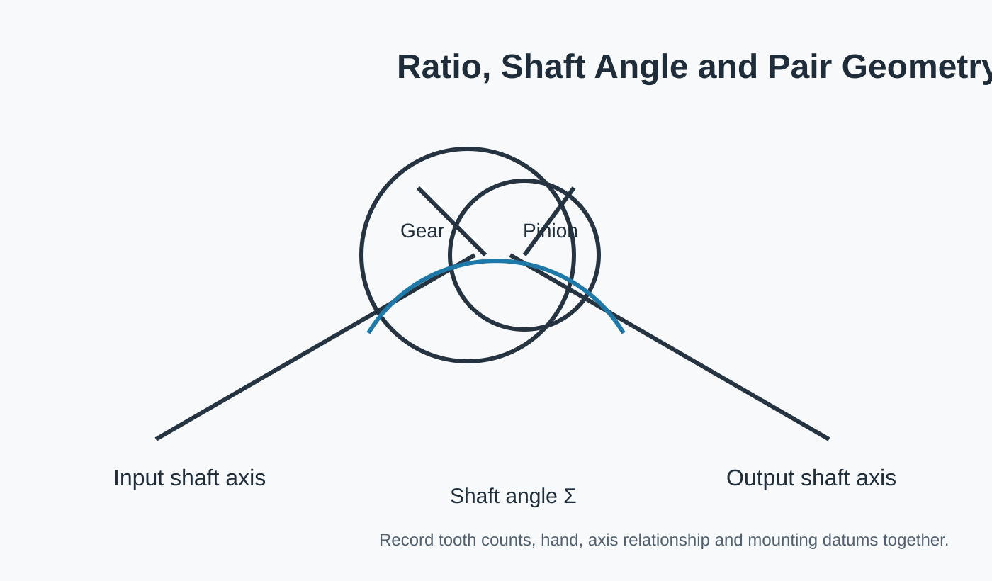
Bilgi tabanındaki diyagramlar, şaft açısı, el, montaj pozisyonu ve temas hareketi gibi kavramları göstermektedir. Bunlar kasıtlı olarak genel niteliktedir. Bir çizimdeki boyut veya geometriyi üretim çizimine kopyalamayın. Sipariş edilen konfigürasyon, onaylanmış proje verileriyle tanımlanmalıdır.
Ürün Tanımı ZD Yüksek Elektrik Gücü Düşük Gürültü Uygun Açılı Spiral Konik İçi Boş Şaft BLDC Fırçasız DC Dişli Motor Çözüm Tanımı Fırçasız DC dişli motor şu özelliklere sahiptir…
Makaleyi okuyun →Ürün Açıklaması: JinXiang, Almanya'dan ithal edilen Çin'in önde gelen 5 eksenli CNC işleme merkezi DEPO XPERT V3520'ye sahiptir; X ekseni hareket mesafesi 3500 mm, Y ekseni hareket mesafesi 2000 mm'dir…
Makaleyi okuyun →Ürün Açıklaması: Özel yapım yüksek hassasiyetli spiral açılı düz konik dişli, gönye kesme ekipmanı, pirinç plastik tekerlekler, helisel pinyon dişliler. Daha fazla bilgi için buraya tıklayın…
Makaleyi okuyun →Ürün Tanımı: spiral konik ekipman, pompa, yağlama, motosiklet koruma, açılır tavan, motor, Land Rover, vida, konveyör, otomatik direksiyon, elektrik, plastik ekipman…
Makaleyi okuyun →Çözüm Tanımı Üretim birimi Özel yapım Düz ve Spiral Pah Kırma Ekipmanları Hangzhou HUANBALL Uzman özel ve hassas işlenmiş elemanlar. Özelleştirilmiş, anahtar teslimi hassas çözümler sunuyoruz…
Makaleyi okuyun →Ürün Tanımı Hızlı Özellikler Ambalaj ve Tedarik Çözümü Açıklaması HAKKIMIZDA 1. uçtan uca kaynağınız olarak, AT PRECAST, Kaldırma Teknikleri de dahil olmak üzere prekast beton aksesuarları tasarlıyor, paketliyor ve dağıtıyoruz…
Makaleyi okuyun →Ürün Tanımı CL-40.5 JN22(B)-40.5/31.5 Topraklama Anahtarı için Tekli Konik Dişli Açıklamalar: 1. CL-40.5 konik dişli ekipmanı, JN22(B)-40.5/31.5 topraklama anahtarı kılavuzu çalışması için kullanılır, KYN61(C) ve…
Makaleyi okuyun →Ürün Tanımı Ürün Tanımı İşletme Profili 2571 yılında Hangzhou CZPT CZPT Co.,ltd, Bayan Iris ve 2 ortağı (Bay Tian ve Bay Yang) tarafından Hangzhou'da kurulmuştur…
Makaleyi okuyun →Ürün Tanımı: Rekabetçi Fiyat Etiketiyle Antika Spiral Dişli Kamyon Dişlisi (Yağ Makinesi/Kamyon için) Detaylı Görseller Kuruluş Profili Sertifikalar Avantajlarımız Personelimiz…
Makaleyi okuyun →