What a Spiral Bevel Gear Tooth Contact Pattern Can Tell You

A tooth contact pattern can be a useful window into how a spiral bevel pair is meeting, but it is not a complete diagnosis by itself. The pattern depends on pair geometry, mounting position, load, checking method and the condition of the housing and bearings. A useful inspection record therefore states how the pattern was obtained, not only what it looked like.

Contact position should be discussed with the checking condition

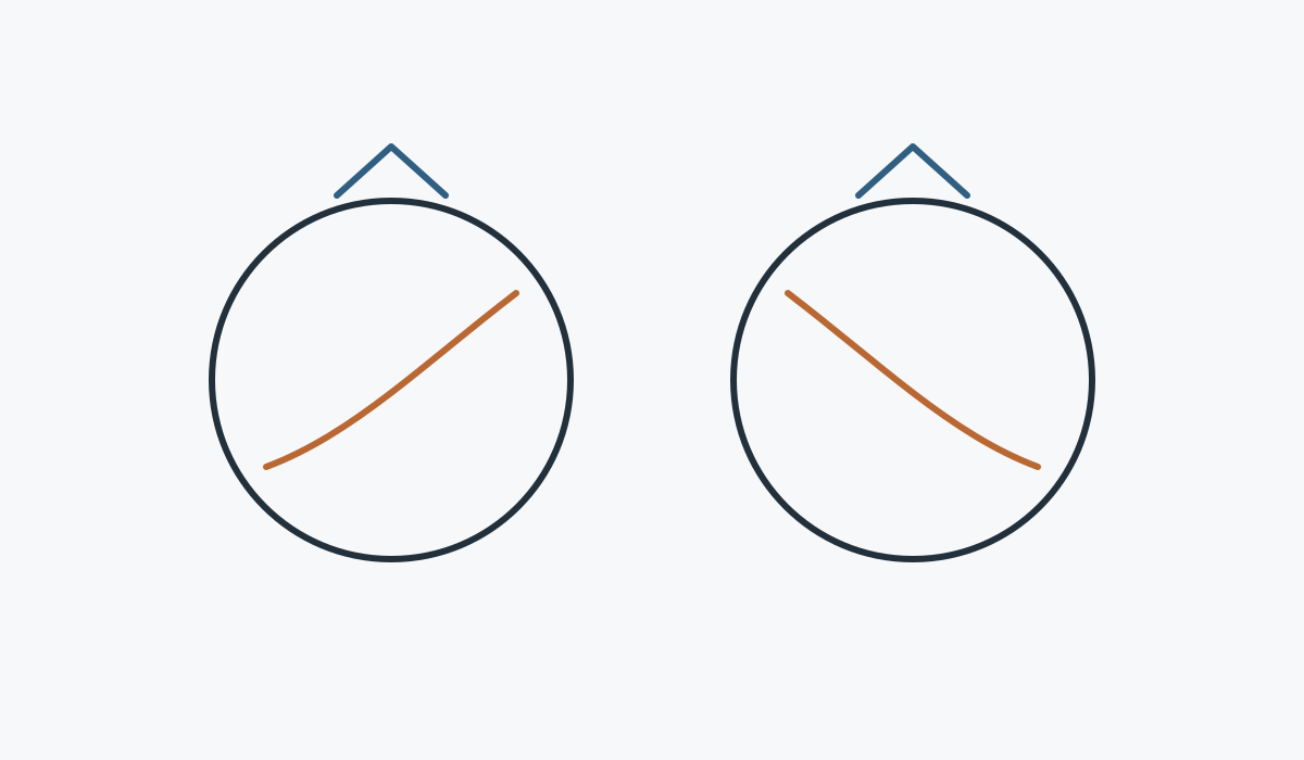
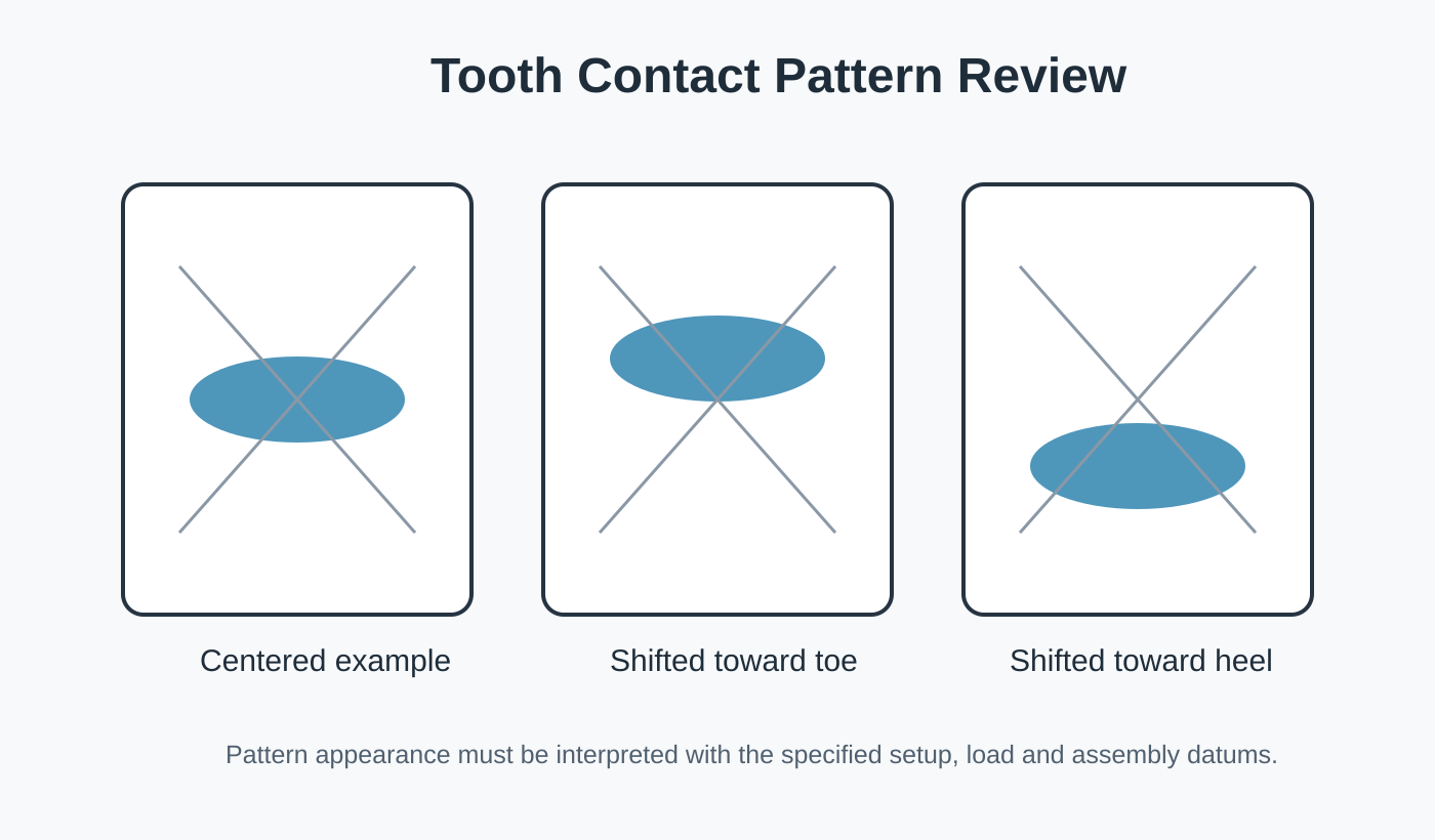
A pattern that appears centered under one light-load checking method may move under operating load or when the mounting position changes. Toe/heel and face/root shifts can be useful observations, but they should be interpreted against the drawing, mounting distance and specified inspection procedure.

This is especially important in replacement work, where worn bearings or a distorted housing can change the pattern independently of the new gear geometry.

Examples of centered and shifted spiral bevel gear contact patterns

Information to record with a pattern

Record Why it matters
Which member drives Contact can be discussed differently depending on the driving direction.
Rotation direction Reversing applications may load different tooth surfaces.
Checking load / method A light marking check and an operating-load pattern are not the same condition.
Mounting position Mounting distance, shims and bearing condition influence the result.
Backlash The assembly state should be recorded with the contact check.
Pair identity The result belongs to the specific gear and pinion being checked.

Use contact review as part of a wider inspection plan

Dimensional and tooth-quality checks tell the buyer whether the individual components meet their controlled requirements. Contact review adds information about how the pair works together in a defined setup. Both are more useful when the same datums and assembly assumptions are documented from the beginning.

Inspection workflow for spiral bevel gear manufacturing

What a pattern cannot prove on its own

A contact pattern by itself does not prove material, heat treatment, tooth accuracy, bearing condition or long-term performance. It should not be used to turn an unknown replacement sample into an exact technical claim. Use it as one piece of evidence in a controlled review of the pair and the assembly.

A practical contact-review checklist

Before comparing patterns, confirm that the same pair, rotation direction, mounting position, backlash and checking method are being used. Photograph the marked teeth with enough context to identify the gear and orientation. If an adjustment is made, record what changed before taking the next image.

That sequence turns the pattern into a useful inspection record. Without the setup information, two images can look different for reasons that have nothing to do with tooth manufacturing.

Questions buyers often ask

Is a centered pattern always correct?

Not by itself. The acceptable location depends on the design, checking method and specified condition. Use the project inspection requirement rather than a generic photo.

Can contact pattern diagnose a bad bearing?

It may show that the pair position has changed, but it does not identify the cause on its own. Bearing condition, housing, mounting and gear geometry must be reviewed together.

Should contact checking be included in every order?

Include it when it is part of the drawing, acceptance plan or project requirement. Do not add a test merely as decoration if it does not help the buyer release the part.

Be om et tilbud

Send girparet, tegningen og oppgaven i én tilbudsforespørsel.

Jo tydeligere paringsforholdet og monteringsdatumene er definert, desto raskere kan konfigurasjonen gjennomgås.

Bestillings- og leveringsveiledning

MOQ er fleksibel avhengig av produkttype, produksjonsrute og total ordreverdi. Egnede nye prosjekter kan be om 1–5 prøvestykker til prøvepris. Blandede modeller kan kombineres når den totale ordresummen når omtrent USD 1500. Bestillinger på 1–2 stykker kan vurderes, selv om enhetskostnaden vanligvis er høyere.

Typiske planleggingsvinduer er 10–25 virkedager for standarddeler, 20–45 virkedager for tilpassede komponenter og 45–120 virkedager for prosjektutstyr eller sammenstillinger. EXW, FOB, CIF og DAP støttes vanligvis; FCA, CFR, CPT, CIP og DDP kan diskuteres for forsendelsen.

Send forespørsel

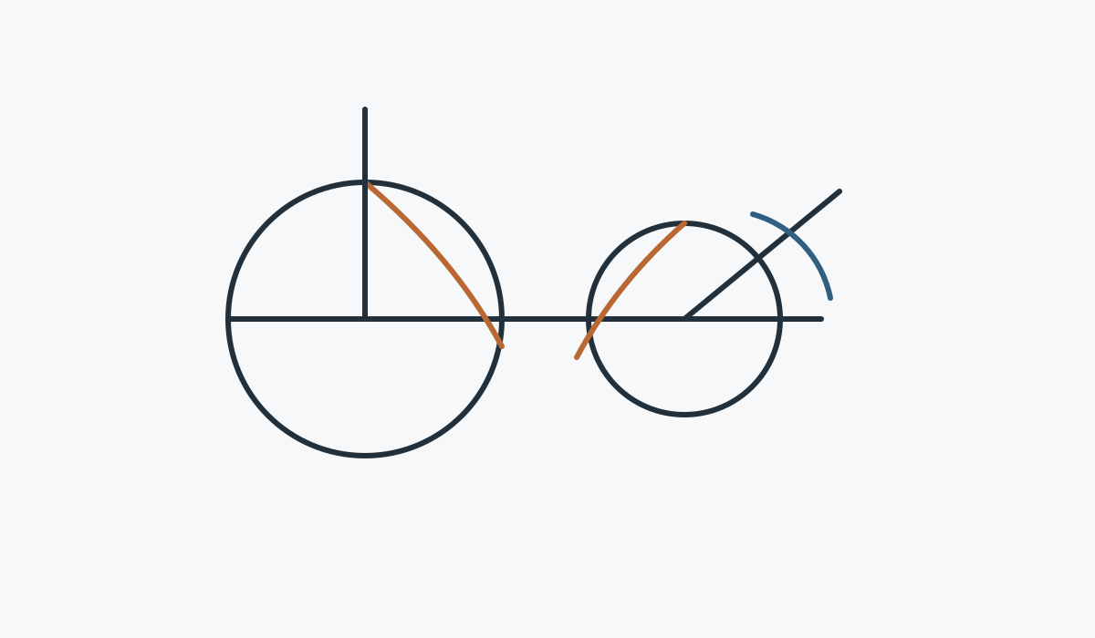
Spiral Bevel Gear Ratio, Shaft Angle and Mounting Geometry

Ratio, shaft angle and mounting geometry answer different questions about the same spiral bevel gear pair. Ratio describes the relationship between the tooth counts. Shaft angle describes how the two axes intersect. Mounting geometry describes where the two finished components are positioned in the housing. Treating any one of these as a complete definition can lead to a pair that looks plausible but does not fit the intended assembly.

Put ratio and axis relationship on the same assembly definition

A ratio can be written as tooth counts or as a numerical relationship, but the drawing should identify which count belongs to the gear and which belongs to the pinion. The shaft angle should be tied to the assembly axes, not inferred from the outside shape of the gear blank.

For replacements, measure the housing or shaft arrangement that establishes those axes. A loose bearing or damaged support can make an “as found” angle misleading.

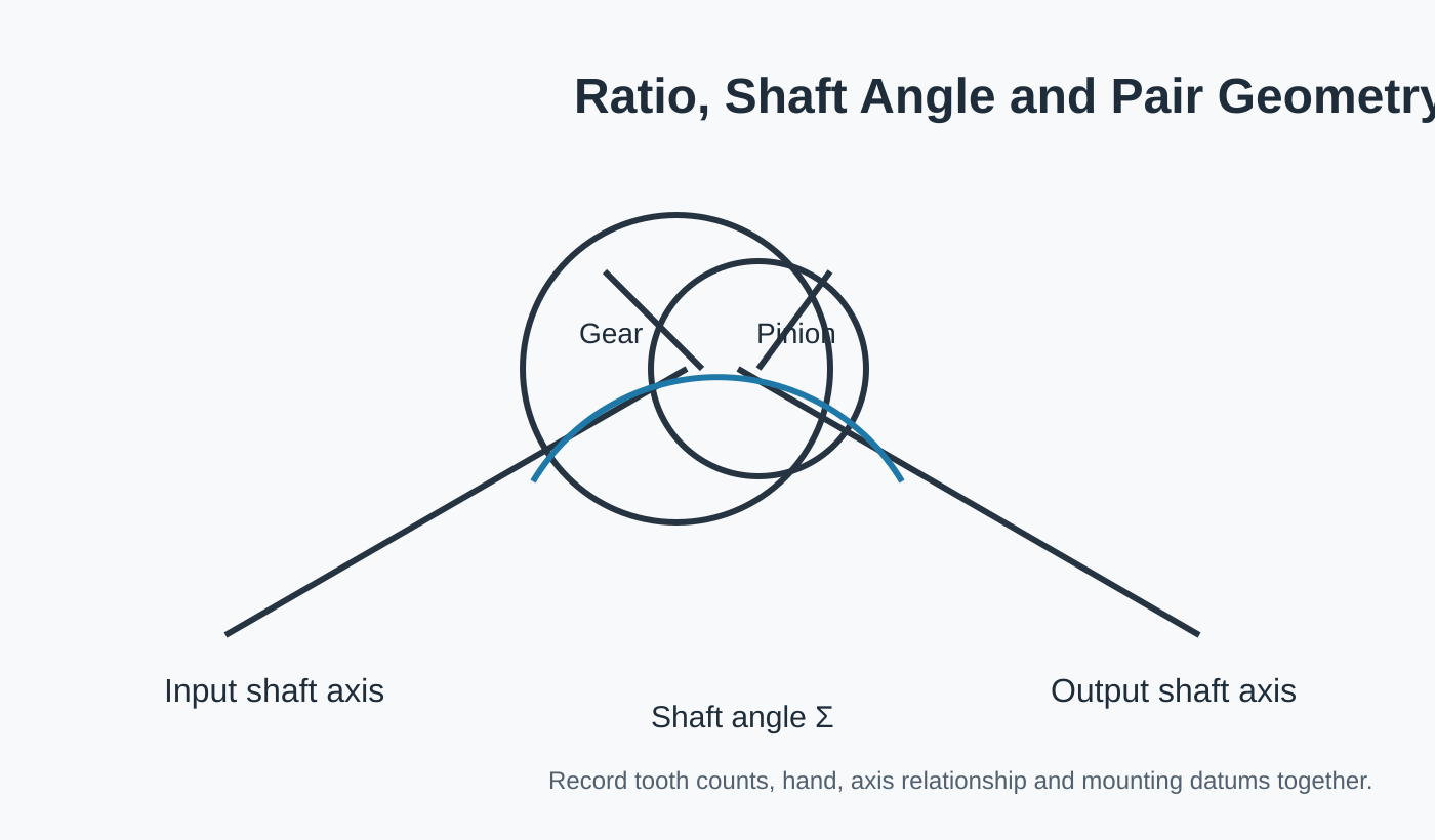
Spiral bevel gear ratio and shaft angle diagram

Four geometry groups to keep together

Geometry group Typical content Why it matters
Ratio Gear and pinion tooth counts Defines the speed/torque relationship of the pair.
Axis relationship Shaft angle and orientation Defines how the two shafts intersect.
Tooth orientation Right/left hand and spiral direction Defines the mating tooth orientation.
Mounting Mounting distance, datums and backlash Defines where the gears sit in the actual housing.

Mounting geometry connects the drawing to the machine

The same tooth geometry can behave differently if the pair is installed away from the intended position. Bearing seats, shoulders and shims can all influence the final location. If backlash or contact is an acceptance item, the drawing and assembly instruction should make the reference condition clear.

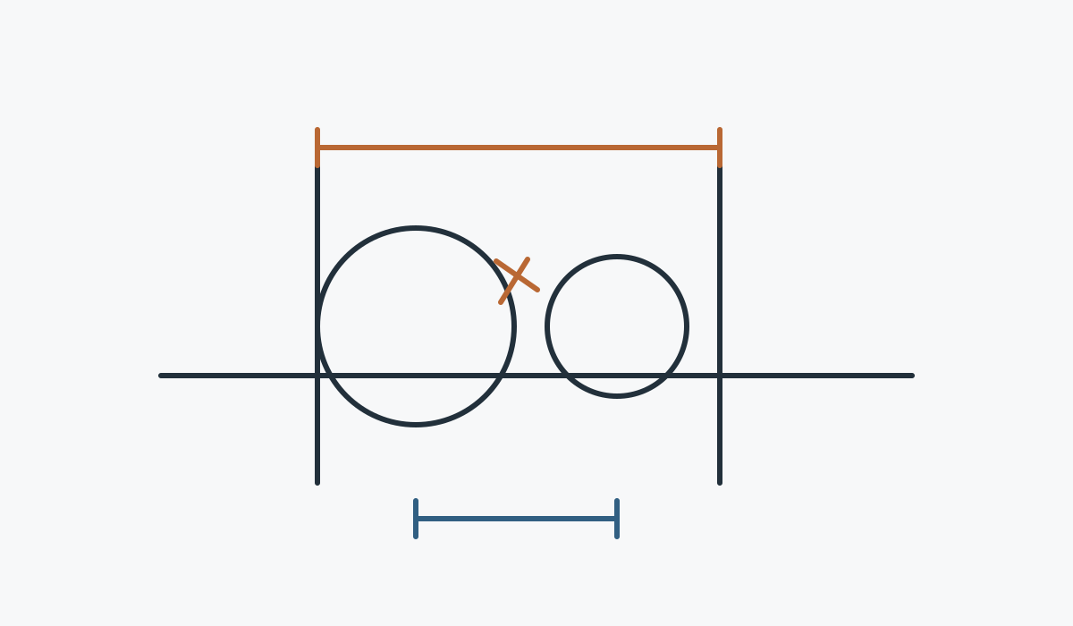
Mounting distance and backlash diagram for a spiral bevel gear assembly

What to send in a replacement RFQ

Send both members if possible, the tooth counts, the orientation of each shaft, the housing/bearing references, measured backlash if reliable, and any legacy drawing. If the original pair is badly worn, document the machine before dismantling so the replacement review can distinguish the intended geometry from the damaged condition.

Common drawing omissions

Drawings sometimes show tooth count and outside dimensions but omit the axis relationship or the mounting reference. Others list a ratio without identifying which member is the pinion. These omissions are manageable during design, but they become expensive when a supplier must reconstruct intent from separate emails.

Use an assembly view or clear notes to connect the pair. If the shaft angle is not the common arrangement for your machine, make it impossible to overlook. If the pair is a replacement, show the existing housing axes and the datum surfaces used for measurement.

Questions buyers often ask

Does 1:1 ratio automatically mean a miter gear set?

Equal tooth count is consistent with a miter arrangement, but the hand, shaft angle and mounting geometry still need to be defined.

Can shaft angle be measured from the gear faces?

Use the actual shaft or housing axes when possible. Gear faces may not be the controlled assembly references.

Why include mounting data on a tooth-geometry drawing?

Because the pair must be positioned correctly in the machine. Mounting information links the manufactured geometry to the working assembly.

Be om et tilbud

Send girparet, tegningen og oppgaven i én tilbudsforespørsel.

Jo tydeligere paringsforholdet og monteringsdatumene er definert, desto raskere kan konfigurasjonen gjennomgås.

Bestillings- og leveringsveiledning

MOQ er fleksibel avhengig av produkttype, produksjonsrute og total ordreverdi. Egnede nye prosjekter kan be om 1–5 prøvestykker til prøvepris. Blandede modeller kan kombineres når den totale ordresummen når omtrent USD 1500. Bestillinger på 1–2 stykker kan vurderes, selv om enhetskostnaden vanligvis er høyere.

Typiske planleggingsvinduer er 10–25 virkedager for standarddeler, 20–45 virkedager for tilpassede komponenter og 45–120 virkedager for prosjektutstyr eller sammenstillinger. EXW, FOB, CIF og DAP støttes vanligvis; FCA, CFR, CPT, CIP og DDP kan diskuteres for forsendelsen.

Send forespørsel

Replacement Spiral Bevel Gears: Identification Checklist

A replacement spiral bevel gear project is an identification problem before it is a manufacturing problem. Wear, broken teeth, loose bearings and field modifications can change the part you see on the bench. The goal is to reconstruct the intended pair and mounting relationship rather than copy every damaged feature.

Record the complete assembly before dismantling

Photograph both members in position, mark the driving and driven components, record rotation if it matters, and measure the housing or bearing references that establish the gear position. If backlash can be measured reliably, record the method and assembly state.

These notes often become more valuable after the worn parts are removed, because the original relationship is otherwise difficult to reconstruct.

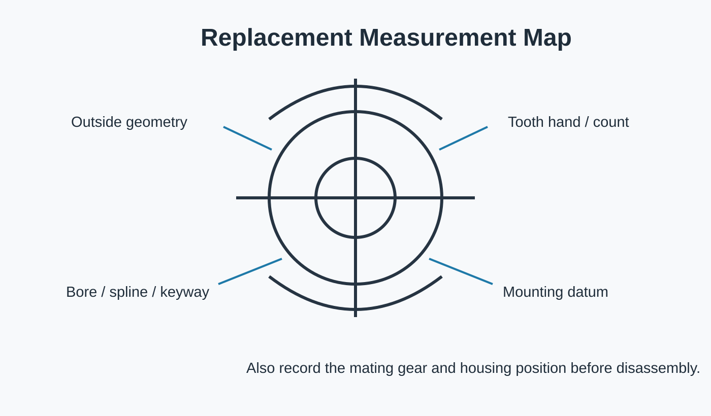
Measurement map for replacement spiral bevel gear identification

Identification checklist

Evidence What it can help establish Caution
Mating gear Ratio/tooth counts, hand and pair relationship Inspect its wear and confirm it actually belongs to the same assembly.
Legacy drawing Original geometry, interfaces and acceptance notes Check revision and whether field modifications occurred.
Part number Identification and historical reference Do not assume a number alone proves the current geometry.
Worn sample Interface dimensions, tooth count, general geometry Wear/damage can hide the original tooth or mounting condition.
Housing measurements Mounting position and shaft relationship Use defined datums and note damaged bearings or looseness.
Photos before removal Orientation and assembly sequence Include a scale/reference and label viewing direction.

Separate damage evidence from design geometry

Chipped tooth tips, pitting, polished contact areas and enlarged bores describe how the old part has lived. They can help a failure review, but they should not automatically become dimensions in the replacement drawing. Use undamaged areas, the mate and assembly data to establish the new controlled definition.

Generic tooth contact pattern positions used during replacement review

When only one member can be replaced

If the mating gear must remain in service, provide as much reliable data as possible: tooth count, hand, original drawing or scan, mounting position, visible condition and any quality information. Exact compatibility should not be promised until that relationship has been reviewed. In some cases the safer project may be a new matched pair rather than one replacement member.

Packing a physical sample

Protect teeth and datum surfaces from further damage. Identify which marks are existing service damage and which were added for orientation. Include a simple packing note that links each sample to the drawing/reference used in the RFQ so multiple parts are not mixed during review.

Before shipping a sample for review

Clean only enough to expose useful surfaces and markings; do not grind or polish away wear evidence. Protect the teeth, bearing seats and datum faces during packing. If two members belong together, tag them as one pair and include an orientation note. If several similar gears are shipped, assign each sample a unique reference that matches the RFQ and photos.

Include a short “known / unknown” sheet. It should state which values come from a drawing, which were measured from the worn sample, and which still need review. This prevents a bench measurement from being mistaken for an original design value.

Questions buyers often ask

Can one worn gear be enough to make a replacement?

Sometimes there is enough reliable information, but it should not be assumed. The mate, housing measurements or legacy data can be essential for reconstructing the original pair.

Should I replace both members?

That depends on the condition and how well the remaining mate is defined. A new matched pair may reduce uncertainty when the existing mate is badly worn or undocumented.

Can a part number identify the gear exactly?

It is useful evidence, but revisions and field changes can exist. Combine the reference with current measurements and the mating relationship.

Be om et tilbud

Send girparet, tegningen og oppgaven i én tilbudsforespørsel.

Jo tydeligere paringsforholdet og monteringsdatumene er definert, desto raskere kan konfigurasjonen gjennomgås.

Bestillings- og leveringsveiledning

MOQ er fleksibel avhengig av produkttype, produksjonsrute og total ordreverdi. Egnede nye prosjekter kan be om 1–5 prøvestykker til prøvepris. Blandede modeller kan kombineres når den totale ordresummen når omtrent USD 1500. Bestillinger på 1–2 stykker kan vurderes, selv om enhetskostnaden vanligvis er høyere.

Typiske planleggingsvinduer er 10–25 virkedager for standarddeler, 20–45 virkedager for tilpassede komponenter og 45–120 virkedager for prosjektutstyr eller sammenstillinger. EXW, FOB, CIF og DAP støttes vanligvis; FCA, CFR, CPT, CIP og DDP kan diskuteres for forsendelsen.

Send forespørsel

Material and Heat Treatment Questions for Spiral Bevel Gears

Material and heat treatment should be tied to the ordered duty and drawing requirements. Two spiral bevel gears can look almost identical while using different material routes because the load spectrum, wear requirement, shock, tooth finish or secondary machining is different. The RFQ should state what is controlled and leave open items clearly marked for review.

Think of material, heat treatment and finishing as one route

The selected material has to support the heat-treatment plan and the final machining sequence. Bores, splines, keyways, threads and datum faces may be finished before or after treatment depending on the design. Tooth grinding, when required, also changes how allowances and datums are protected.

That is why an alloy name by itself is not enough to describe the manufacturing requirement.

Manufacturing route from machining through heat treatment and inspection

Questions to answer in the RFQ

Question What to state
Is the material fixed? Exact grade/specification if controlled; otherwise mark for project review.
Is heat treatment controlled? Method and any hardness/case requirements exactly as the drawing specifies.
Which features are acceptance-critical? Tooth finish, bore/spline, journals, mounting faces and any controlled runout or dimensions.
Will secondary machining follow heat treatment? Identify features that must remain machinable or be finish-machined later.
What is the duty? Load spectrum, speed, reversals, shock, environment and lubrication context.

Heavy-duty does not mean “pick the hardest material”

Higher hardness is not a universal answer. Material condition, case/core relationship, toughness, geometry and the rest of the assembly all matter. Use the design requirement or a project-specific review rather than maximizing one property without considering manufacturing and service.

Heavy-duty spiral bevel gear pair for load-sensitive applications

Replacement projects need extra caution

A worn sample may not reveal the original material condition reliably. If a legacy drawing, material certificate, historical inspection or unused reference part exists, include it. Otherwise describe the machine duty and clearly identify the material as an item to be reviewed before the replacement drawing is approved.

Common specification mistakes

One common mistake is copying a material and hardness from an unrelated gear that happens to be the same size. Another is specifying heat treatment without considering which bores, splines or datum faces still need machining. A third is writing a very tight hardness or case requirement without defining where it is measured or why it is needed.

Use the controlled design requirement when it exists. When it does not, state the duty and ask for a reviewed proposal rather than manufacturing a false sense of precision.

Questions buyers often ask

Can the supplier recommend a material?

A supplier can review options when the duty and geometry are understood, but the final ordered material should be agreed explicitly rather than left implied.

Should hardness be listed on the RFQ?

List it when it is a controlled requirement. If it is not fixed, provide the duty and allow the heat-treatment route to be reviewed with the material choice.

Why do bore and spline details matter to heat treatment?

Those features may need allowance, masking or finish machining. Their sequence can affect distortion control and the datum strategy used for final inspection.

Be om et tilbud

Send girparet, tegningen og oppgaven i én tilbudsforespørsel.

Jo tydeligere paringsforholdet og monteringsdatumene er definert, desto raskere kan konfigurasjonen gjennomgås.

Bestillings- og leveringsveiledning

MOQ er fleksibel avhengig av produkttype, produksjonsrute og total ordreverdi. Egnede nye prosjekter kan be om 1–5 prøvestykker til prøvepris. Blandede modeller kan kombineres når den totale ordresummen når omtrent USD 1500. Bestillinger på 1–2 stykker kan vurderes, selv om enhetskostnaden vanligvis er høyere.

Typiske planleggingsvinduer er 10–25 virkedager for standarddeler, 20–45 virkedager for tilpassede komponenter og 45–120 virkedager for prosjektutstyr eller sammenstillinger. EXW, FOB, CIF og DAP støttes vanligvis; FCA, CFR, CPT, CIP og DDP kan diskuteres for forsendelsen.

Send forespørsel

Ground vs Cut Spiral Bevel Gears: What Changes in the RFQ?

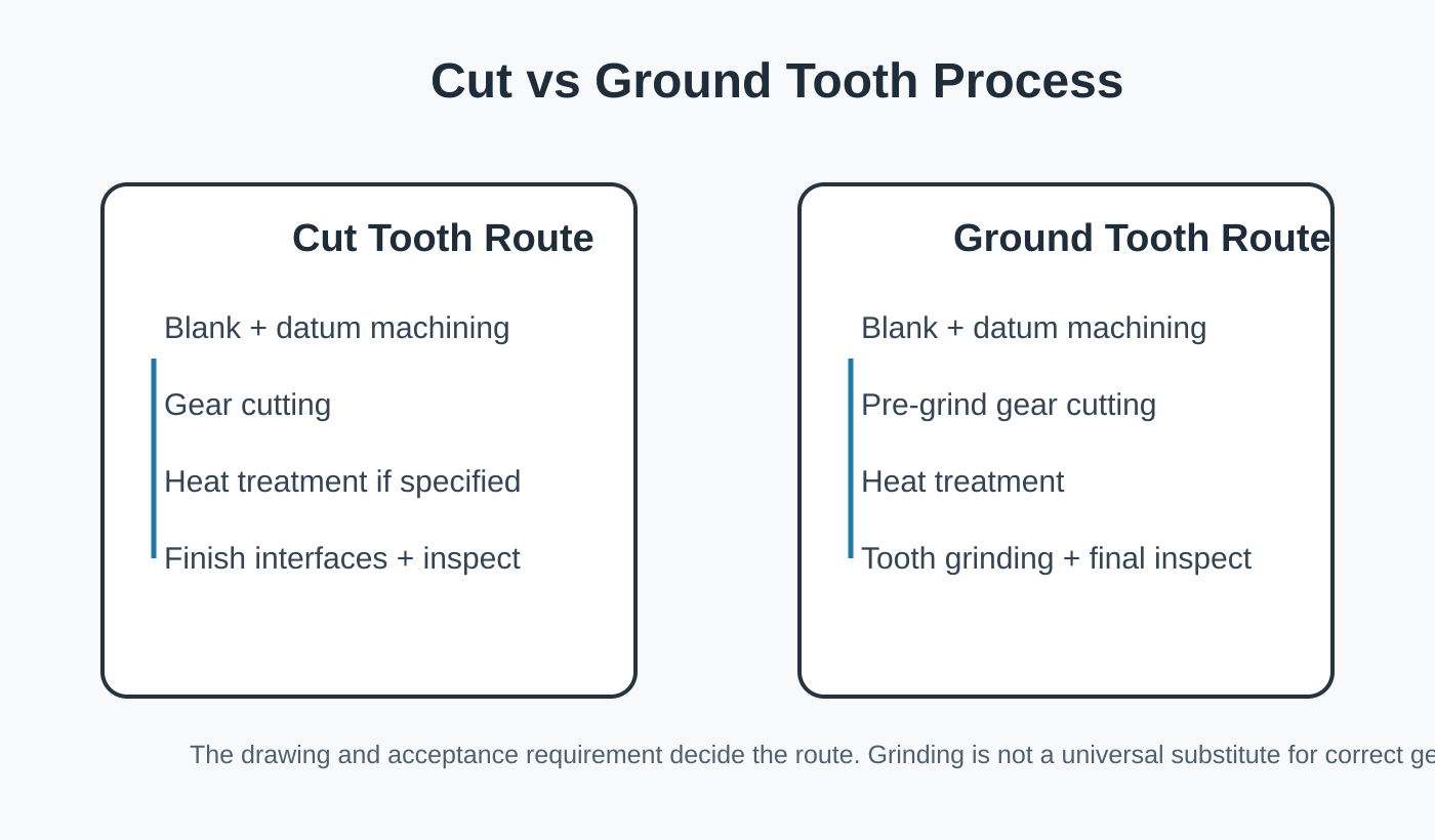
“Ground” and “cut” describe manufacturing routes, not a simple quality ranking. The correct choice starts with the drawing, duty and acceptance requirement. If a ground tooth finish is specified, heat treatment, datum protection, grinding allowance and final inspection have to be planned around that route from the beginning.

The process diverges before the last operation

A cut-tooth gear may be finished by the specified cutting and heat-treatment route without a final tooth-grinding stage. A ground-tooth gear normally needs a controlled pre-grind condition and stable datums that survive heat treatment so the tooth surface can be finished afterward.

That difference affects planning, cost and inspection. It should therefore be stated in the RFQ rather than added after a quote is already based on another route.

Comparison of cut and ground spiral bevel gear process routes

What changes in the RFQ

RFQ area Cut-tooth route Ground-tooth route
Tooth finish State the required cut finish and quality/inspection criteria State the ground tooth requirement and finished quality/inspection criteria
Heat treatment Specify if required by the design Coordinate heat treatment with grinding allowance and datum protection
Datums Needed for gear cutting and interface inspection Needed before heat treatment and again for final grinding/inspection
Inspection Dimensional and tooth-related checks to drawing Final tooth and interface checks after the grinding route
Commercial impact Generally simpler route when technically suitable Additional finishing and inspection stages should be included from the first quote

Grinding does not correct an undefined assembly

A precisely finished tooth surface still needs the correct mating geometry and mounting position. If the shaft angle, hand or mounting distance is wrong, choosing a ground finish does not make the pair compatible. The product drawing and assembly relationship remain the first decision.

Matched spiral bevel gear pair geometry

When to ask for a ground tooth finish

Use the ground route when the drawing, performance requirement or controlled manufacturing plan calls for it. Avoid specifying grinding only because it sounds more precise. The useful question is whether the machine needs a finished-tooth condition and inspection level that justify the route.

If the requirement is still open, describe the duty, positioning sensitivity, expected service and inspection needs so the process can be reviewed without turning a marketing preference into a technical constraint.

How to compare quotations for the two routes

Compare more than the final unit price. Confirm whether the quotations assume the same material, heat-treatment route, tooth finish, inspection scope and quantity. A ground-tooth quotation may include additional stages that a cut-tooth quotation does not. If those assumptions are not written down, two prices can appear different even though they are not quoting the same technical outcome.

For prototypes, ask whether later repeat production will use the same process route and inspection plan. That avoids approving a sample made one way and receiving production made another way without a controlled change.

Questions buyers often ask

Is a ground gear always quieter?

Noise depends on the full pair, geometry, mounting, housing, lubrication and operating condition. A ground finish alone does not guarantee a machine-level noise result.

Can a cut gear be upgraded to ground after heat treatment?

The route needs grinding allowance, suitable datums and process planning from the start. Do not assume a finished cut gear can simply be ground later.

Which route should I request if the drawing does not specify one?

Describe the duty and acceptance need, then review the appropriate route. Avoid adding a manufacturing process only for perceived prestige.

Be om et tilbud

Send girparet, tegningen og oppgaven i én tilbudsforespørsel.

Jo tydeligere paringsforholdet og monteringsdatumene er definert, desto raskere kan konfigurasjonen gjennomgås.

Bestillings- og leveringsveiledning

MOQ er fleksibel avhengig av produkttype, produksjonsrute og total ordreverdi. Egnede nye prosjekter kan be om 1–5 prøvestykker til prøvepris. Blandede modeller kan kombineres når den totale ordresummen når omtrent USD 1500. Bestillinger på 1–2 stykker kan vurderes, selv om enhetskostnaden vanligvis er høyere.

Typiske planleggingsvinduer er 10–25 virkedager for standarddeler, 20–45 virkedager for tilpassede komponenter og 45–120 virkedager for prosjektutstyr eller sammenstillinger. EXW, FOB, CIF og DAP støttes vanligvis; FCA, CFR, CPT, CIP og DDP kan diskuteres for forsendelsen.

Send forespørsel

Mounting Distance and Backlash in Spiral Bevel Gear Assemblies

Mounting distance and backlash connect the gear geometry to the housing, bearings and shaft stack. They are not independent numbers that can be copied from a similar-looking gear. A useful RFQ defines where each value is measured and which assembly surfaces hold the pair in that position.

Mounting distance needs a real datum

A value becomes useful only when the reference surface, shoulder, axis or housing feature is defined. Put that datum on the drawing. If the project is a replacement, record the assembly before the old gears and bearings are removed.

When several surfaces could be used as references, identify the one that actually controls the position in service rather than the easiest surface to reach with a caliper.

Mounting distance and backlash relationship in a spiral bevel gear assembly

Why backlash is an assembly outcome

Backlash is influenced by the gear geometry and by how the two members are positioned. Bearing seats, shims, shoulders and housing tolerances all contribute. If the machine specifies a backlash range, include that requirement and explain the assembly condition under which it is checked.

For precision or reversing mechanisms, the buyer may also care about repeatability after reversal. That should be described as an application requirement rather than hidden inside a vague request for “minimum backlash.”

What to measure during replacement work

Measurement area Recommended record
Gear position Distance from defined mounting face/shoulder to the relevant gear reference
Shaft support Bearing locations, shoulders and any shims that establish axial position
Mating gear Tooth count, hand, bore/shaft interface and installed orientation
Backlash Measured range and the method/assembly state used to obtain it
Housing Critical distances between shaft or bearing references
Condition Wear, looseness or damage that may have changed the measured position

Do not use wear as the datum

A worn thrust face, damaged bearing or loosened shaft can change the apparent position of the gear. Note the condition of the assembly and separate “as found” measurements from the intended design reference. Legacy drawings or an undamaged mating member can help reconstruct the original position.

Replacement measurement map for a spiral bevel gear assembly

RFQ wording that reduces ambiguity

State the mounting distance with its reference, the backlash target with its checking condition, and whether the housing/bearing arrangement will remain unchanged. If adjustment is available through shims or another mechanism, describe the available range. That information lets the supplier understand whether the gear geometry must hit one fixed position or be installed within an adjustable system.

Fixed versus adjustable mounting

Some assemblies locate the pair with fixed shoulders and bearing seats; others use shims or another adjustment method. State which arrangement you have. In a fixed housing, the replacement geometry has less freedom to compensate for an incorrect position. In an adjustable assembly, the available range should be documented so the installation procedure and backlash target are understood together.

Do not hide an unknown housing dimension behind a wide backlash range. The supplier still needs the geometry that establishes the intended position.

Questions buyers often ask

Can backlash be set after installation?

Sometimes the assembly provides an adjustment method, but that depends on the actual housing and bearing arrangement. State the available adjustment and the target checking condition.

Is mounting distance the same as overall gear length?

No. Mounting distance is tied to a defined gear/assembly reference. Overall length may be useful for packaging, but it does not by itself define the working position.

Should I measure a worn assembly before changing bearings?

Yes. Record the as-found condition first, then note any bearing or shim changes separately so the original and corrected positions are not mixed.

Be om et tilbud

Send girparet, tegningen og oppgaven i én tilbudsforespørsel.

Jo tydeligere paringsforholdet og monteringsdatumene er definert, desto raskere kan konfigurasjonen gjennomgås.

Bestillings- og leveringsveiledning

MOQ er fleksibel avhengig av produkttype, produksjonsrute og total ordreverdi. Egnede nye prosjekter kan be om 1–5 prøvestykker til prøvepris. Blandede modeller kan kombineres når den totale ordresummen når omtrent USD 1500. Bestillinger på 1–2 stykker kan vurderes, selv om enhetskostnaden vanligvis er høyere.

Typiske planleggingsvinduer er 10–25 virkedager for standarddeler, 20–45 virkedager for tilpassede komponenter og 45–120 virkedager for prosjektutstyr eller sammenstillinger. EXW, FOB, CIF og DAP støttes vanligvis; FCA, CFR, CPT, CIP og DDP kan diskuteres for forsendelsen.

Send forespørsel

How Right- and Left-Hand Spiral Bevel Gears Work as a Pair

Right- and left-hand descriptions are part of the mating relationship, not decorative labels. A spiral bevel pair is designed so the two members mesh with the intended hand, ratio, shaft relationship and mounting position. When one of those items is recorded without a defined viewing convention, an RFQ can become ambiguous very quickly.

Record the hand of both members with a defined viewing direction

Photograph or sketch the gear and pinion from a known side and label the viewing direction. If the original drawing contains a hand designation, keep that wording with the drawing revision. For replacement work, show both members together before disassembly if possible.

The goal is not to teach the supplier a generic naming rule; it is to make your specific pair impossible to misread.

Right- and left-hand spiral bevel gear relationship

Hand is only one part of the pair definition

Pair variable Question to answer
Hand / spiral direction How is each member designated and from which viewing direction?
Ratio / tooth counts How many teeth are on the gear and pinion?
Shaft angle What is the included angle between the two axes?
Mounting position Which surfaces or axes locate each member in the housing?
Backlash Is there a specified operating or assembly range?

Rotation changes which tooth surfaces carry load

The active contact surface depends on the direction of rotation and which member drives. If the machine routinely reverses, state that in the application data. It can affect how the buyer wants the pair inspected or evaluated in the assembly.

Do not infer the direction of load from a single static photo. Describe the operating direction or provide an assembly sketch.

Generic tooth contact positions for a spiral bevel gear pair

Replacement work needs the mating gear

A worn single gear may still reveal tooth count and hand, but it does not automatically reveal the complete original geometry. The mate, housing dimensions, legacy drawing or an unused reference part can provide information that wear has obscured. If only one member is being replaced, its relationship to the remaining gear must be reviewed before manufacturing.

What to send with the enquiry

Include clear orientation photos, both tooth counts, any original part number, the shaft angle, the mating component and the drawing or housing references used to set the gear position. Mark unknown items as unknown instead of assigning a hand or mounting value from appearance alone.

Common hand-identification mistakes

Three mistakes appear repeatedly in replacement enquiries. The first is labeling only one member without showing the mate. The second is calling a hand from an undefined viewing direction. The third is assuming that the direction of rotation automatically defines the hand. Keep those concepts separate: record the tooth orientation, show the viewing direction and then describe operating rotation as application information.

When several photos are supplied, mark one as the reference view and label the gear and pinion consistently. A simple annotation on the photo is often more useful than a long email description.

Questions buyers often ask

Can right- and left-hand gears be swapped?

Do not assume they can. The pair is designed around a specific tooth orientation and mating relationship. Review both members and the drawing before changing hand.

Does reversing rotation require a different gear pair?

Not automatically. Reversal changes which tooth surfaces carry load, so the operating cycle should be part of the application review.

What if the original hand marking is missing?

Use the physical pair, a defined viewing direction, clear photos and any legacy drawing to establish the orientation before the replacement drawing is approved.

Be om et tilbud

Send girparet, tegningen og oppgaven i én tilbudsforespørsel.

Jo tydeligere paringsforholdet og monteringsdatumene er definert, desto raskere kan konfigurasjonen gjennomgås.

Bestillings- og leveringsveiledning

MOQ er fleksibel avhengig av produkttype, produksjonsrute og total ordreverdi. Egnede nye prosjekter kan be om 1–5 prøvestykker til prøvepris. Blandede modeller kan kombineres når den totale ordresummen når omtrent USD 1500. Bestillinger på 1–2 stykker kan vurderes, selv om enhetskostnaden vanligvis er høyere.

Typiske planleggingsvinduer er 10–25 virkedager for standarddeler, 20–45 virkedager for tilpassede komponenter og 45–120 virkedager for prosjektutstyr eller sammenstillinger. EXW, FOB, CIF og DAP støttes vanligvis; FCA, CFR, CPT, CIP og DDP kan diskuteres for forsendelsen.

Send forespørsel

How to Prepare a Spiral Bevel Gear RFQ

A spiral bevel gear RFQ becomes easier to quote when the buyer sends the information that defines the mating pair instead of only a photo and outside diameter. The strongest enquiries combine a controlled drawing or usable sample with assembly context, duty, quantity and a clear list of what the delivered part must be checked against.

Start with the pair, not the single gear

Identify the gear and pinion together. Include which member drives, their tooth counts or ratio, right- and left-hand relationship, shaft angle and any known mounting-distance or backlash requirement. If the job is a replacement, the mating part can reveal information that a worn single component no longer shows clearly.

A photograph is valuable for orientation, damage and packaging context, but it cannot prove the original tooth geometry. The drawing or a controlled reconstruction of the pair must carry that responsibility.

Show ratio, shaft angle and hand on one controlled definition

These variables describe different parts of the mating relationship. Ratio or tooth count tells how the members relate kinematically; shaft angle describes the axis relationship; hand and spiral direction describe the tooth orientation. Put them together in the drawing or assembly note so they cannot be interpreted independently.

Ratio and shaft angle information for a spiral bevel gear RFQ

Put geometry and interfaces into one package

RFQ item What to send Why
Mating pair Gear + pinion identity, tooth counts/ratio and hand Prevents a single component from being quoted against an unknown mate.
Shaft relationship Shaft angle and assembly orientation Defines how the two axes intersect.
Mounting position Mounting distance, housing/bearing datums and target backlash Connects the tooth geometry to the real assembly.
Interfaces Bore, spline, keyway, shaft, flange and bearing journals Ensures the part can be located and assembled correctly.
Material / finish Material, heat treatment, tooth finish and controlled hardness/case requirements Defines the required manufacturing route.
Acceptance Tolerances, quality standard, runout/contact checks and required records Defines how the buyer will release the finished part.

Show the assembly datum scheme

A drawing that specifies tooth geometry but omits the housing or shaft references can still leave a manufacturing question: how is the gear located in the actual assembly? Add shoulders, bearing seats, flange faces or housing dimensions that control the mounting position. This is especially important when backlash or contact pattern is sensitive to assembly stack-up.

For a replacement, record those references before the old pair is removed. Once worn parts are on a bench, some useful installation information may be lost.

Mounting distance and backlash relationship in a spiral bevel gear assembly

Define the process outcome you actually need

State the required material and heat treatment when they are controlled by the design. State whether the teeth are cut or ground and which quality or inspection standard applies. Avoid copying a hardness or quality grade from another gear unless it belongs to the same design requirement.

When you are comparing possible production routes, an external forged bevel gear manufacturing reference can be useful background for blank and manufacturing terminology. The production drawing and accepted quotation still control the actual spiral bevel gear order.

Add duty and commercial scope before the quote is finalized

Operating speed, torque or load spectrum, reversals, shock, lubrication and environment help the supplier understand why the drawing contains certain material, tooth-finish or inspection requirements. Quantity, destination and sample needs matter to setup, packing and logistics. Putting these items in the first RFQ makes later price comparisons more meaningful because suppliers are quoting the same scope.

Commercial planning for your RFQ

For request a quote planning, MOQ is flexible and depends on product form, processing route and overall order value. Suitable new projects may be reviewed for 1–5 sample pieces at sample pricing. Different models can be combined when the order total reaches about USD 1,500. Orders of 1–2 pieces can also be considered, usually at a higher unit cost because setup and inspection are spread across a very small quantity.

For request a quote delivery planning, typical windows are 10–25 working days for standard parts, 20–45 working days for customized components and 45–120 working days for project-type equipment or assemblies. EXW, FOB, CIF and DAP are commonly supported; FCA, CFR, CPT, CIP and DDP can be discussed for the specific shipment and destination.

Final RFQ checklist

  • Current controlled drawing or the clearest available legacy data
  • Gear + pinion relationship and quantities
  • Ratio/tooth counts, tooth system, hand and shaft angle
  • Mounting datums, backlash target and assembly context
  • Bore, spline, keyway, shaft or flange interfaces
  • Material, heat treatment, finish and quality requirements
  • Duty, environment and lubrication context
  • Inspection records required with the shipment
  • Destination, sample quantity and preferred Incoterm
Be om et tilbud

Send girparet, tegningen og oppgaven i én tilbudsforespørsel.

Jo tydeligere paringsforholdet og monteringsdatumene er definert, desto raskere kan konfigurasjonen gjennomgås.

Bestillings- og leveringsveiledning

MOQ er fleksibel avhengig av produkttype, produksjonsrute og total ordreverdi. Egnede nye prosjekter kan be om 1–5 prøvestykker til prøvepris. Blandede modeller kan kombineres når den totale ordresummen når omtrent USD 1500. Bestillinger på 1–2 stykker kan vurderes, selv om enhetskostnaden vanligvis er høyere.

Typiske planleggingsvinduer er 10–25 virkedager for standarddeler, 20–45 virkedager for tilpassede komponenter og 45–120 virkedager for prosjektutstyr eller sammenstillinger. EXW, FOB, CIF og DAP støttes vanligvis; FCA, CFR, CPT, CIP og DDP kan diskuteres for forsendelsen.

Send forespørsel

China supplier Carburized and Quenching/ Tempering/ Nitriding/ Carbonitriding/ Teeth Induction Hardening Bevel Gear/ Spur Gear/ Spiral Gear/Helical Gear for Agriculture portable air compressor

China Supplier Carburized and Quenching/ Tempering/ Nitriding/ Carbonitriding/ Teeth Induction Hardening Bevel Gear/ Spur Gear/ Spiral Gear/ Helical Gear for Agriculture Portable Air Compressor

Product Description

CHINAMFG offers a wide range of high-quality gears that are essential for various industrial applications. Our extensive gear manufacturing experience enables us to provide different types of gears, including Spur Gear, Helical Gear, Straight Bevel Gear, Spiral Bevel Gear, and Worm Gear. Equipped with advanced CNC gear hobbing, helical gear broaching, and gear grinding machines, as well as state-of-the-art testing equipment like gear profile measuring instruments and hardness testing instruments, we ensure excellent manufacturing and quality control capabilities to deliver superior gears to our customers.

Modulus M0.5-M12
Processing Machine Forging, Machining, Hobbing Teeth, Milling Teeth, Shaving Teeth, Grinding Teeth, and more
Material 20CrMnTi/ 20CrMnMo/ 42CrMo/ C45/ 40Cr/ SS304/ Brass, and more
Heat Treatment Carburizing and Quenching/ Tempering/ Nitriding/ Carbonitriding/ Induction Hardening
Hardness 58-62HRC
Quality Standard GB/ DIN/ JIS/ AGMA
Accuracy Class 5-8 class

Bevel Gear Internal Gear Ring Small Module Gear Made of Brass

Workshop

Our well-equipped workshop includes CNC lathes, CNC hobbing teeth machines, CNC broaching teeth machines, CNC grinding teeth machines, as well as carburizing and quenching equipment and teeth profile measuring instruments. With these advanced facilities, we ensure precise manufacturing and high-quality products.

FAQ

Q1: Are you a trading company or manufacturer?
A: We are a factory.

Q2: What is your delivery time and shipment?
1. Sample Lead-times: 10-20 days.
2. Production Lead-times: 30-45 days after order confirmation.

Q3: What are your advantages?
1. We offer the most competitive prices without compromising quality.
2. Our team of experienced technical engineers provides excellent support.
3. We offer OEM services.

Q4: What other products does your company supply?
Our company specializes in supplying various industrial products, including agricultural gearboxes, power output shafts, sprockets, fluid couplings, worm gear reducers, gears and racks, roller chains, pulleys, planetary gearboxes, timing pulleys, bushings, and more.

Q5: Can you customize products based on our drawings and samples?
Yes, we welcome customization and can manufacture products based on your drawings and samples.

All content on this page is from the Internet and is for reference purposes only. Our products are replacement parts and not original spare parts. We are not the holder of the original trademarks of the content. Our replacement parts can be perfectly adapted to the original spare parts. However, if you need to purchase original spare parts, please contact the original factory or supplier.

Spiral gears are a type of gear that is commonly used in machinery applications. They are designed to transmit power between parallel or perpendicular shafts at a right angle. The spiral shape of the gear teeth allows for smoother and more precise operation compared to other types of gears.

When selecting spiral gears for your machinery, it is important to consider factors such as the power requirements of your application, the speed of the gears, and the load capacity. It is also important to consider the material of the gears, as this can affect their durability and lifespan.

At our company, we offer a range of high-quality replacement spiral gears that are designed to meet the needs of various machinery applications. Our replacement parts are carefully crafted to ensure optimal performance and reliability. Whether you need spiral gears for industrial machinery or other applications, we have the parts you need to keep your equipment running smoothly.

Please note that our replacement parts are not original spare parts and are not affiliated with the original manufacturers of the equipment. Our parts are only suitable for after-sales replacement purposes and are not intended to be used as original spare parts. If you require original spare parts, please contact the original factory or supplier to purchase them.

Performance Characteristics of Spiral Gear

Spiral gears possess several performance characteristics that make them highly desirable in various applications. Firstly, they offer high torque transmission capability, enabling them to handle heavy loads efficiently. Secondly, these gears provide smooth and quiet operation, reducing noise and vibration. Thirdly, they exhibit excellent meshing performance, resulting in high efficiency and minimal power loss. Lastly, spiral gears have strong resistance to shock and impact, making them suitable for rugged environments. Each of these characteristics contributes to the overall effectiveness of spiral gears in different industries.

Types and Characteristics of Spiral Gear

Spiral gears come in different types, each with its own unique characteristics. One common type is the straight-tooth spiral gear, which offers a high load capacity and smooth operation. Another type is the helical-tooth spiral gear, known for its exceptional meshing performance and quiet operation. Additionally, the double helical-tooth spiral gear provides improved load distribution and enhanced stability. The choice of spiral gear type depends on specific application requirements, such as load capacity, noise level, and operational environment.

Moreover, the characteristics of spiral gears can be further enhanced by using different materials. Steel spiral gears offer high strength and durability, making them suitable for demanding applications. Aluminum spiral gears, on the other hand, provide lightweight and corrosion resistance, ideal for aerospace and marine applications. Furthermore, plastic spiral gears offer low friction and self-lubrication properties, reducing the need for additional lubrication. The selection of spiral gear material depends on factors such as operating conditions, desired performance, and cost-effectiveness.

Application of Spiral Gear

The versatility of spiral gears is evident in their wide range of applications across various industries. In the automotive transmissions sector, spiral gears play a crucial role in transferring power efficiently and smoothly. In the aerospace industry, these gears are utilized in aircraft engines and landing gear systems for reliable and precise motion control. Industrial machinery heavily relies on spiral gears for power transmission and motion control in manufacturing processes.

Spiral gears also find extensive use in power tools, providing the necessary torque and speed for efficient operation. Additionally, in marine applications, these gears enable propulsion and maneuverability of ships and boats. The ability of spiral gears to excel in these diverse fields reflects their value and importance in various industries, contributing to the overall advancement and efficiency of different sectors.

Future Development Trends and Opportunities

The future of spiral gear products holds promising trends and opportunities. With advancements in technology, there is a growing demand for gears with higher load capacity, improved efficiency, and reduced noise levels. Additionally, as industries strive for more sustainable solutions, there is an increasing focus on designing spiral gears with eco-friendly materials and manufacturing processes.

Moreover, the rise of automation and robotics presents new opportunities for spiral gears in precision motion control systems. These gears can be customized to meet the unique requirements of automated machinery, enabling smooth and accurate operation. Furthermore, the expanding renewable energy sector offers potential applications for spiral gears in wind turbines and solar power systems.

By capitalizing on these development trends and embracing new opportunities, the spiral gear industry can continue to grow and innovate, further enhancing its contribution to various sectors.

Choosing a Suitable Spiral Gear

Selecting the right spiral gear involves considering several crucial aspects. Firstly, the load requirements must be assessed to ensure the gear can handle the intended application’s torque and power demands. Secondly, the gear ratio needs to be determined, taking into account the desired speed and motion requirements. Thirdly, material selection should be based on factors such as strength, durability, and environmental considerations.

Efficiency and backlash are also essential considerations, as gears with higher efficiency and minimal backlash result in smoother and more precise operation. Finally, mounting and space constraints should be evaluated to ensure the selected spiral gear can be properly installed within the available space.

By carefully analyzing these aspects, one can make an informed decision when choosing a suitable spiral gear that meets the specific requirements of the desired application.

Conclusion

In conclusion, spiral gears possess performance characteristics that make them highly effective in various applications. Their diverse types and characteristics provide flexibility and adaptability to different operational needs. The choice of material further enhances their performance, catering to specific industry requirements. The wide-ranging applications of spiral gears reflect their significance in various fields, contributing to the advancement and efficiency of industries.

Looking ahead, the future of spiral gears holds immense potential for further development and innovation. By embracing emerging trends and exploring new opportunities, the industry can continue to evolve and meet the evolving needs of different sectors. Choosing a suitable spiral gear involves a comprehensive evaluation of load requirements, gear ratio, material selection, efficiency, backlash, mounting, and space constraints. By considering these factors, individuals and industries can make informed decisions when selecting spiral gears for their specific applications.

Author: Dream

China Custom Pinion Rack Round Worm Screw Helical Hypoid Straight Ring Spiral Forged Bevel Spur Differential Steering Internal Box Spline Plastic Nylon Stainless Steel Gear manufacturer
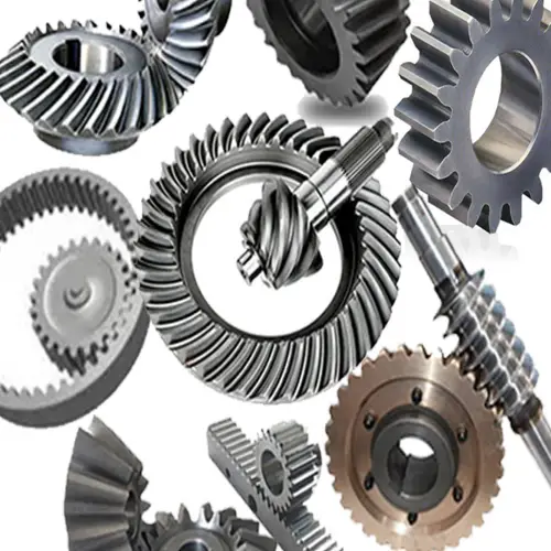
China Custom Gears Manufacturer: Pinion Rack, Round Worm Screw, Helical Hypoid, Straight Ring, Spiral Forged Bevel, Spur, Differential Steering, Internal Box, Spline, Plastic Nylon, Stainless Steel

Our company is a leading gear manufacturer in China, specializing in producing high-quality gears for various industrial applications. We offer a wide range of gear types to choose from, including spur gears, helical gears, bevel gears, spiral bevel gears, straight bevel gears, internal gears, worm gears, gear rack, and more. Our production process involves CNC machining, CNC milling, and cnc lathe machining to ensure precision and accuracy in every gear we produce.

Gear Material Options

We use a variety of materials for our gears, including stainless steel (SS201, SS303, SS304, SS316, SS416, SS420, etc.), steel (C45, 40Cr, 42CrMo, 20CrNiMo, 20CrMnTi, etc.), brass (C36000, C26800, HPb59, C38500, HPb58, CuZn37, CuZn40, etc.), bronze (C51000, C52100, C54400, etc.), iron (1213, 12L14, 1215, etc.), aluminum (Al6061, Al6063, Al2571, Al7075, etc.), and nylon (PA66, MC901, POM, etc.). We also offer various surface treatments such as black oxide, Zn-plated, ni-plated, tin-plated, chrome plated, passivated, sandblast and anodize, chromate, polish, electro painting, black anodize, plain, and H.D.G.

Customization Process

At our company, we support customized gears from customers’ drawings and samples, and we offer various non-standard customization options. The customization process involves several steps:

  1. Product Discussions: Customers send drawings or samples and we quote according to their requirements.
  2. Molds Designing: We design 3D drawings and optimize the products.
  3. Drawing Confirmation: We send the mold drawing to the customers and wait for their confirmation.
  4. Molds Construction: We manufacture molds accurately according to the drawings.
  5. Molds Inspection and Test: We detect various indicators of molds and optimize the inner cavities.
  6. Sample Approval from Customer: Customers approve the samples and confirm them for bulk production.
  7. Mass Production: We produce in bulk according to customers’ PO.

FAQs

1. What types of gears do you offer?

We offer a wide range of gear types, including spur gears, helical gears, bevel gears, spiral bevel gears, straight bevel gears, internal gears, worm gears, gear rack, and more.

2. What materials do you use for your gears?

We use a variety of materials for our gears, including stainless steel, steel, brass, bronze, iron, aluminum, and nylon.

3. Can you customize gears according to our drawings and samples?

Yes, we support customized gears from customers’ drawings and samples, and we offer various non-standard customization options.

4. What is your quality control process?

We have ISO9001 and ISO14001 certifications, and we conduct 100% factory inspections to ensure the quality of our products. We also offer a long quality guarantee and fast response to customers’ feedbacks.

5. What other products do you offer besides gears?

In addition to gears, we also offer agricultural gearboxes, power output shafts, sprockets, fluid couplings, worm gear reducers, roller chains, pulleys, planetary gearboxes, timing pulleys, bushings, and more. Customers are welcome to customize drawings and samples for all of our products.

All content on this page is from the Internet and is for reference purposes only. Our products are replacement parts and not original spare parts. We are not the holder of the original trademarks of the content. Our replacement parts can be perfectly adapted to the original spare parts. However, if you need to purchase original spare parts, please contact the original factory or supplier.

Spiral gears are a type of gear that is commonly used in machinery applications. They are designed to transmit power between parallel or perpendicular shafts at a right angle. The spiral shape of the gear teeth allows for smoother and more precise operation compared to other types of gears.

When selecting spiral gears for your machinery, it is important to consider factors such as the power requirements of your application, the speed of the gears, and the load capacity. It is also important to consider the material of the gears, as this can affect their durability and lifespan.

At our company, we offer a range of high-quality replacement spiral gears that are designed to meet the needs of various machinery applications. Our replacement parts are carefully crafted to ensure optimal performance and reliability. Whether you need spiral gears for industrial machinery or other applications, we have the parts you need to keep your equipment running smoothly.

Please note that our replacement parts are not original spare parts and are not affiliated with the original manufacturers of the equipment. Our parts are only suitable for after-sales replacement purposes and are not intended to be used as original spare parts. If you require original spare parts, please contact the original factory or supplier to purchase them.

Performance Characteristics of Spiral Gear

Spiral gears possess several performance characteristics that make them highly desirable in various applications. Firstly, they offer high torque transmission capability, enabling them to handle heavy loads efficiently. Secondly, these gears provide smooth and quiet operation, reducing noise and vibration. Thirdly, they exhibit excellent meshing performance, resulting in high efficiency and minimal power loss. Lastly, spiral gears have strong resistance to shock and impact, making them suitable for rugged environments. Each of these characteristics contributes to the overall effectiveness of spiral gears in different industries.

Types and Characteristics of Spiral Gear

Spiral gears come in different types, each with its own unique characteristics. One common type is the straight-tooth spiral gear, which offers a high load capacity and smooth operation. Another type is the helical-tooth spiral gear, known for its exceptional meshing performance and quiet operation. Additionally, the double helical-tooth spiral gear provides improved load distribution and enhanced stability. The choice of spiral gear type depends on specific application requirements, such as load capacity, noise level, and operational environment.

Moreover, the characteristics of spiral gears can be further enhanced by using different materials. Steel spiral gears offer high strength and durability, making them suitable for demanding applications. Aluminum spiral gears, on the other hand, provide lightweight and corrosion resistance, ideal for aerospace and marine applications. Furthermore, plastic spiral gears offer low friction and self-lubrication properties, reducing the need for additional lubrication. The selection of spiral gear material depends on factors such as operating conditions, desired performance, and cost-effectiveness.

Application of Spiral Gear

The versatility of spiral gears is evident in their wide range of applications across various industries. In the automotive transmissions sector, spiral gears play a crucial role in transferring power efficiently and smoothly. In the aerospace industry, these gears are utilized in aircraft engines and landing gear systems for reliable and precise motion control. Industrial machinery heavily relies on spiral gears for power transmission and motion control in manufacturing processes.

Spiral gears also find extensive use in power tools, providing the necessary torque and speed for efficient operation. Additionally, in marine applications, these gears enable propulsion and maneuverability of ships and boats. The ability of spiral gears to excel in these diverse fields reflects their value and importance in various industries, contributing to the overall advancement and efficiency of different sectors.

Future Development Trends and Opportunities

The future of spiral gear products holds promising trends and opportunities. With advancements in technology, there is a growing demand for gears with higher load capacity, improved efficiency, and reduced noise levels. Additionally, as industries strive for more sustainable solutions, there is an increasing focus on designing spiral gears with eco-friendly materials and manufacturing processes.

Moreover, the rise of automation and robotics presents new opportunities for spiral gears in precision motion control systems. These gears can be customized to meet the unique requirements of automated machinery, enabling smooth and accurate operation. Furthermore, the expanding renewable energy sector offers potential applications for spiral gears in wind turbines and solar power systems.

By capitalizing on these development trends and embracing new opportunities, the spiral gear industry can continue to grow and innovate, further enhancing its contribution to various sectors.

Choosing a Suitable Spiral Gear

Selecting the right spiral gear involves considering several crucial aspects. Firstly, the load requirements must be assessed to ensure the gear can handle the intended application’s torque and power demands. Secondly, the gear ratio needs to be determined, taking into account the desired speed and motion requirements. Thirdly, material selection should be based on factors such as strength, durability, and environmental considerations.

Efficiency and backlash are also essential considerations, as gears with higher efficiency and minimal backlash result in smoother and more precise operation. Finally, mounting and space constraints should be evaluated to ensure the selected spiral gear can be properly installed within the available space.

By carefully analyzing these aspects, one can make an informed decision when choosing a suitable spiral gear that meets the specific requirements of the desired application.

Conclusion

In conclusion, spiral gears possess performance characteristics that make them highly effective in various applications. Their diverse types and characteristics provide flexibility and adaptability to different operational needs. The choice of material further enhances their performance, catering to specific industry requirements. The wide-ranging applications of spiral gears reflect their significance in various fields, contributing to the advancement and efficiency of industries.

Looking ahead, the future of spiral gears holds immense potential for further development and innovation. By embracing emerging trends and exploring new opportunities, the industry can continue to evolve and meet the evolving needs of different sectors. Choosing a suitable spiral gear involves a comprehensive evaluation of load requirements, gear ratio, material selection, efficiency, backlash, mounting, and space constraints. By considering these factors, individuals and industries can make informed decisions when selecting spiral gears for their specific applications.

Author: Dream
Redigert av Zqq.
Send forespørsel