
Machine duty
Explain peak and continuous load, start/stop frequency, shock events, braking, direction changes, shaft support and inspection access. These inputs help the quotation reflect the actual machine rather than an industry label.
Lifting and hoist mechanisms place the emphasis on load spectrum, starts and stops, shock, braking events, support stiffness and inspection access. Nominal torque alone is not enough to describe the duty.
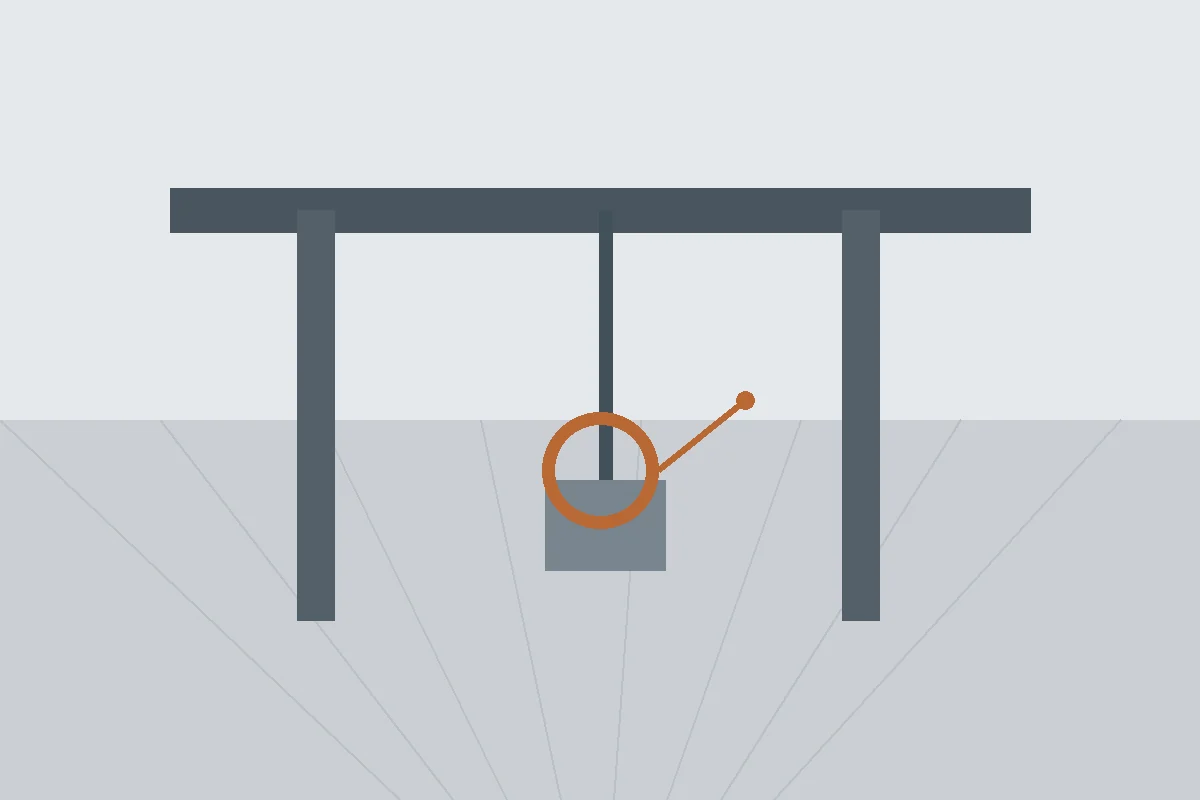
Heavy-duty transmissions need a clear picture of how the load reaches the gear pair and how the shafts are supported. Bearing arrangement and housing stiffness matter because tooth contact depends on the position of the two members under load.
For maintenance replacements, add inspection history, visible damage and any measured changes in backlash. Damage patterns can help explain the service problem, but they should not be copied into the new geometry as if wear were part of the original design.
Explain peak and continuous load, start/stop frequency, shock events, braking, direction changes, shaft support and inspection access. These inputs help the quotation reflect the actual machine rather than an industry label.
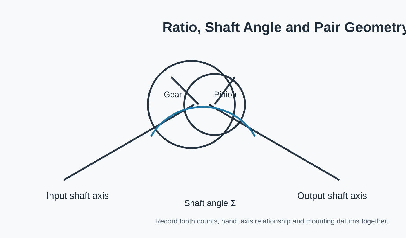
Identify both members, tooth counts or ratio, hand and which component drives.
Show the shaft angle, mounting references, bearing positions and any controlled backlash.
State the inspection or contact checks that matter to release the part for this machine.
| Review area | What to provide | Why it matters |
|---|---|---|
| Motion / duty | Peak and continuous load, start/stop frequency, shock events, braking, direction changes, shaft support and inspection access | Separates steady power transmission from reversing, shock or position-sensitive duty. |
| Gear pair | Gear + pinion identity, ratio/tooth counts and hand | Prevents one component from being reviewed without its mating geometry. |
| Mounting | Shaft arrangement, bearing support, housing datums and target backlash | Connects the manufactured part to the position it will hold in the assembly. |
| Environment | Lubrication, temperature and contamination context | Supports practical material, finish and service review without inventing machine-level claims. |
| Inspection | Drawing tolerances, tooth finish and required records | Defines what the buyer will use to accept the ordered configuration. |
A single “maximum torque” value can hide frequent starts, impact events or reversing load. Send the load spectrum and duty cycle when available, and identify whether the pair is exposed to overload or emergency events that the design must consider.
Heavy-duty or custom spiral bevel gear pairs are appropriate starting pages. Ground tooth finishing should be specified only when the drawing or performance requirement calls for that manufacturing route.
If a lifting or hoisting mechanism still has open geometry or duty inputs, mark those items for review. An explicit unknown is safer than filling the drawing with an assumed standard value.
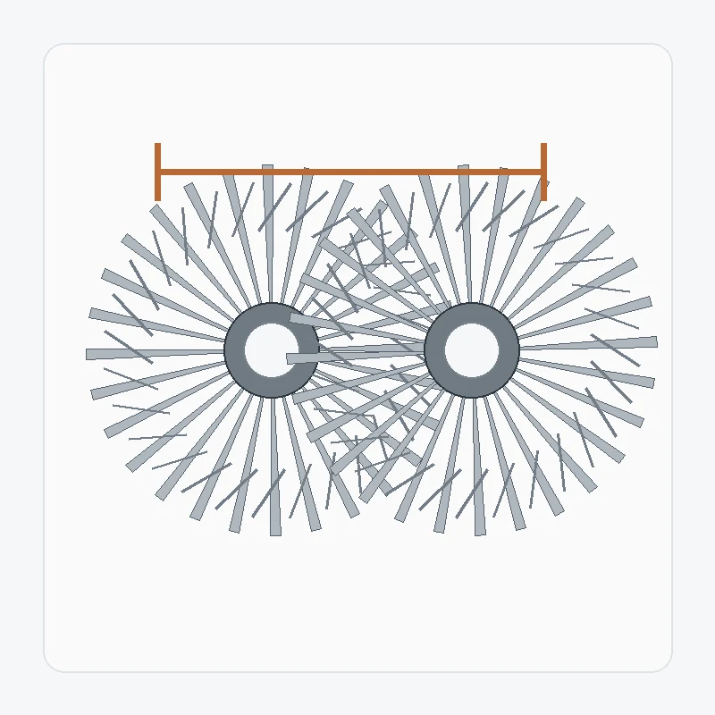
Replacement spiral bevel gear work begins by separating original design information from service wear. A damaged tooth, distorted bore or shifted contact pattern can describe the failure, but…
View configuration →
A heavy-duty spiral bevel gear pair should be reviewed from the complete operating duty. Peak load, continuous load, shock events, reversals, bearing support and lubrication can all matter…
View configuration →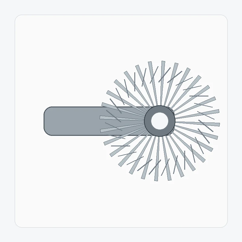
Integrating the spiral bevel pinion with a shaft reduces separate joints, but it makes bearing journals, shoulders, splines, threads and tooth datums part of one manufacturing problem. The…
View configuration →
A spiral miter gear set uses equal tooth counts to transmit motion between intersecting shafts without intentionally changing speed ratio. Equal ratio simplifies one part of the selection,…
View configuration →
Ground spiral bevel gears require more than adding a grinding operation to a normal gear. The datum scheme, pre-grind geometry, heat treatment, grinding allowance and final inspection have…
View configuration →
A custom spiral bevel gear set is built around project-specific geometry rather than a public stock table. The useful definition includes both members of the pair, the axis…
View configuration →When the lifting or hoisting mechanism drawing controls material or heat treatment, include the exact requirement. If those choices remain open, describe the duty and leave material/process selection for review.
Photos of the lifting or hoisting mechanism help establish orientation and condition, but they do not define tooth geometry or mounting datums. Add the mating member, drawing data and measurements taken from controlled assembly references.
For the lifting or hoisting mechanism, send the assembly information that controls shaft relationship, mounting datums and interfaces. Unrelated machine details can be omitted when they have no effect on gear selection or inspection.
For the lifting or hoisting mechanism, separate prototype/sample quantity from expected repeat demand. This keeps tooling, inspection and production planning tied to the real purchasing stage.
The more clearly the mating relationship and assembly datums are defined, the faster the configuration can be reviewed.
MOQ is flexible by product type, manufacturing route and total order value. Suitable new projects may request 1–5 sample pieces at sample pricing. Mixed models can be combined when the order total reaches approximately USD 1,500. Orders of 1–2 pieces can be reviewed, although unit cost is normally higher.
Typical planning windows are 10–25 working days for standard parts, 20–45 working days for customized components and 45–120 working days for project-type equipment or assemblies. EXW, FOB, CIF and DAP are commonly supported; FCA, CFR, CPT, CIP and DDP can be discussed for the shipment.