Сипаттама
Ауыр жүктемелі спиральды конус тәрізді тісті доңғалақ жұбын толық пайдалану мерзімінен бастап қайта қарау керек. Ең жоғары жүктеме, үздіксіз жүктеме, соққы оқиғалары, кері бұрылыстар, мойынтірек тірегі және майлау материал мен технологиялық шешімдерге әсер етуі мүмкін. Нақты геометрия сызбаға байланысты болып қала береді.
Ең жақсы бастапқы нүкте: Жүктеме спектрі, соққы, іске қосу/тоқтату немесе тірек қаттылығы қарапайым номиналды-айналдырғыш момент сипаттамасына қарағанда жұмысты талап ететін жоба.
Бұл өнім тобы нені шешуге арналған
Берілісті «ауыр жүктемеге төзімді» деп атау техникалық сипаттаманы жасамайды. RFQ нақты жүктемені және жұпты қолдайтын құрастыруды қажет етеді. Бұл ақпарат қолдау көрсетілмейтін өнімділік белгісіне қарағанда пайдалырақ.
Жүктеме және қызмет көрсету міндеті басым мәселелер болған кезде осы бетті пайдаланыңыз. Егер негізгі талап тегістеу тісі болса, тегістеуден бастаңыз; егер жоба ескі ауыр жұпты ауыстырса, алдымен сәйкестендіру мәселесі шешілуі үшін ауыстыру бетін пайдаланыңыз.
Техникалық сипаттама және RFQ кестесі
Ауыр жүктемелі спиральды конус тәрізді тісті доңғалақ жұбы үшін реттелген конфигурация үшін дәл сандық мәндер расталады. Төмендегі кестеде нақты басқаруды қажет ететін сызба және сұрау өрістері көрсетілген.
| Таңдау элементі | Конфигурация | RFQ ескертпесі |
|---|---|---|
| Жұптық сәйкестендіру | Сәйкес келетін спиральды конус тәрізді тісті беріліс жұбы немесе жобаға тән жалғыз компонент | Жұптасатын мүше мен жүргізуші қатынасын растаңыз. |
| Білік бұрышы | Жобаға тән | Ось қатынасын немесе құрастыру сызбасын көрсетіңіз. |
| Тіс санының арақатынасы | Суретке немесе RFQ-ға | Белгілі болған кезде екі тістің санын көрсетіңіз. |
| Модуль / диаметрлік қадам | Суретке немесе RFQ-ға | Тек сыртқы диаметр бойынша бағаламаңыз. |
| Қысым бұрышы | Тапсырыс берілген конфигурация үшін растаңыз | Ауыстыру жұмыстары үшін сызбаны немесе сенімді ескі деректерді пайдаланыңыз. |
| Спираль бұрышы және қол | Тапсырыс берілген конфигурация үшін растаңыз | Көру ережесі анықталған оң/сол қолды анықтаңыз. |
| Орнату қашықтығы / кері соққы | Жобаға тән | Бақылау кезінде тұрғын үй деректерін және нысана ауқымын көрсетіңіз. |
| Ұңғыма / сплайн / білік интерфейсі | Суретке немесе үлгіге | Кілт жолын, сплайн стандартын, журналдарды және деректер талаптарын қосыңыз. |
| Материал / жылумен өңдеу | Суретке немесе жобаға шолу жасауға | Егер бақыланатын болса, міндетті түрде дәрежесін, қаттылығын немесе корпус талаптарын көрсетіңіз. |
| Тістің өңделуі / сапасы | Суретке немесе жобаға шолу жасауға | Мемлекеттік кесу/жерлеу талабы және қабылдау стандарты немесе тексеру критерийлері. |
Байланыс және қолдау жағдайлары жүктеме кезінде маңызды
Материал, термиялық өңдеу және тісті әрлеу жобалау талабы мен жүктеме жағдайына сәйкес таңдалуы керек. Корпус пен мойынтірек жүйесі де мақсатты қалыпта ұстап тұру үшін жеткілікті қаттылықты қажет етеді. Содан кейін тексеру машина үшін маңызды өлшемдер мен тіске қатысты критерийлер бойынша келісіледі.
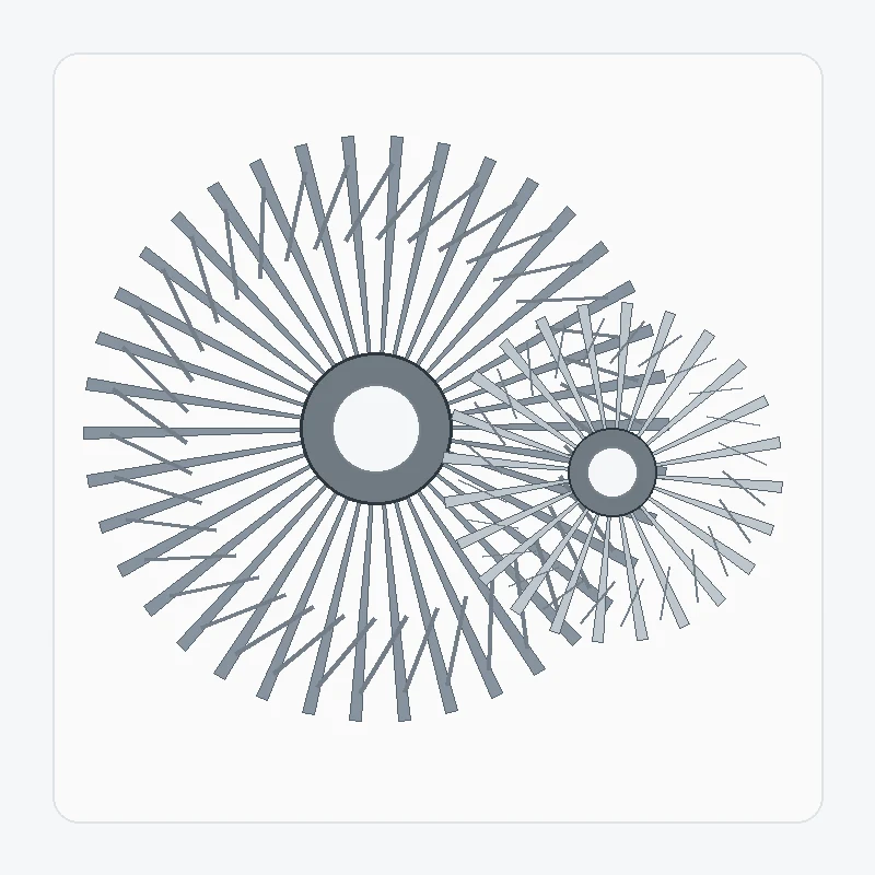
Ауыр жүктемелі спиральды конус тәрізді тісті доңғалақ жұбының техникалық көрінісі компоненттердің өзара байланысын талқылауға көмекші құрал болып табылады. Бақыланатын өндіріс сызбасы және бекітілген баға тапсырыстың өлшемдік анықтамасы болып қала береді.
Интерфейстер және құрастыру тексерулері

Жұптасатын мүше
Қай беріліс қорабы құрамдас бөлікпен үйлесетінін және екі элементтің де қоректену бөлігіне кіретінін растаңыз.

Деректер және орнату
Бекіту қашықтығын, біліктің орналасуын және люфтті басқаратын беттер мен осьтерді көрсетіңіз.

Материалдық бағыт
Бақыланатын материалға/жылулық өңдеуге қойылатын талаптарды белгілеңіз және екінші реттік өңдеуді қажет ететін ерекшеліктерді анықтаңыз.

Қабылдау
Босату үшін қажетті өлшемдік, тіс сапасын, иілу немесе жанасу тексерулерін тізіп шығыңыз.
Әдеттегі қолданбаға сәйкестік
Көтергіш механизмдер, ауыр өнеркәсіптік беріліс қораптары, қуат беру жабдықтары және соққыға төзімді, жоғары жүктемелі немесе күрделі жұмыс циклдары бар басқа да жинақтар.
Материалдың бағытын, тістерді өңдеуді, тірек болжамдарын немесе тексеру талабын өзгертуі мүмкін болған кезде өтінім бажы сызбамен бірге жіберілуі керек.
CNC станоктары

Тік бұрышты жетектері және бекіту қаттылығы мен кері соққы маңызды болатын орналастыру механизмдері.
Қолдану бойынша нұсқаулық →
Робототехника және автоматика

Кері жұмыс және қайталану талаптары бар ықшам қиылысатын ось механизмдері.
Қолдану бойынша нұсқаулық →
Лазерлік кесу және гантри жүйелері

Порттық тіректердің айналасындағы бағытты өзгертетін беріліс қорабы және автоматтандырылған позициялау жабдықтары.
Қолдану бойынша нұсқаулық →
Ауыр заттарды көтеру және көтеру

Соққы беру, іске қосу/тоқтату және қолдау тәртібін қайта қарауды қажет ететін ауыр жүктемелі механизмдер.
Қолдану бойынша нұсқаулық →
Дәлдік машиналары

Бақыланатын деректер, жұмыс уақыты және жанасу талаптары бар ықшам дәлдік жүйелері.
Қолдану бойынша нұсқаулық →
Өнеркәсіптік беріліс қораптары

Айналмалы білік орналасуы арқылы момент беретін беріліс қорабы сатылары.
Қолдану бойынша нұсқаулық →Өндіріс және тексеру реттілігі
Пікір
Суретті қайта қарауды, жұптың сәйкестігін, ашық сұрақтарды және қабылдауға маңызды ерекшеліктерді растаңыз.
Жоспар
Дайындаманы, дәлдікпен өңдеуді, тісті кесуді, термиялық өңдеуді және әрлеу реттілігін анықтаңыз.
Аяқтау
Тапсырыс берілген бағытқа сәйкес тістер мен беттерді толық өңдеу.
Тексеру
Конфигурация үшін келісілген өлшемдер мен беріліске қатысты критерийлерді тексеріңіз.
Сауалнамаға не қосу керек
| RFQ тобы | Ұсынылған мәліметтер |
|---|---|
| Техникалық анықтама | Ағымдағы сызба, жұп сілтемесі, қатынас/тістер саны, қол мен осьтің қатынасы |
| Ассамблея | Скважина/білік/шпинат, мойынтіректер, корпус деректері, орнату қашықтығы және басқарылса, кері серпіліс |
| Міндет | Жылдамдық, айналу моменті/жүктеме спектрі, кері бұрылыстар, соққы, қоршаған орта және майлау |
| Сапа | Материал, термиялық өңдеу, тіс өңдеу, төзімділік және тексеру жазбалары |
| Коммерциялық | Прототип және қайталау саны, тағайындалған жері, уақыт мақсаты және қалаған сауда мерзімі |
Жиі қойылатын сұрақтар
Жұптың тек бір мүшесіне тапсырыс бере аламын ба?
Ауыр жүктемелі спиральды конус тәрізді тісті беріліс жұбы үшін бір элементті жеткізуді жұп толық анықталған кезде қарастыруға болады. Егер бар жұп белгісіз болса, бір компонентті жібермес бұрын оның сызбасын, өлшемдерін немесе физикалық берілісін жіберіңіз.
Тозған үлгіні тікелей көшіруге бола ма?
Тозған ауыр жүктемелі спиральды конус тәрізді тісті доңғалақ жұбының үлгісі идентификацияны қолдай алады, бірақ тозуды түпнұсқа геометрия ретінде қарастыруға болмайды. Ескі сызбалар, пайдаланылмаған түйіспелі элемент және құрастыру өлшемдері қалпына келтірудің берік негізін қамтамасыз етеді.
RFQ алдында материалды және термиялық өңдеуді таңдауым керек пе?
Ауыр жүктемелі спиральды конус тәрізді беріліс жұбының дизайны материалды немесе термиялық өңдеуді басқарған кезде, нақты талапты көрсетіңіз. Егер бұл элементтер ашық болса, басқа берілістен баға алудың орнына, жұмыс уақытын сипаттап, оларды таңдауды қайта қарау үшін белгілеңіз.
Шағын үлгілер қалай өңделеді?
Ауыр жүк көтергіш спиральды конус тәрізді тісті доңғалақ жұбының шағын үлгілерін жаңа жобаларға сәйкес келетіндей етіп қарастыруға болады. Орнату, тексеру және кейінгі өндіріс дұрыс көлемге сәйкес жоспарлануы үшін прототип мөлшерін күтілетін қайталанатын сұраныстан бөліңіз.
Сіздің сұрауыңыз бойынша коммерциялық жоспарлау
Баға сұрауын жоспарлау үшін MOQ икемді және өнім түріне, өңдеу бағытына және тапсырыстың жалпы құнына байланысты. 1-5 үлгі дана үшін сәйкес келетін жаңа жобаларды үлгі бағасымен қарастыруға болады. Тапсырыстың жалпы сомасы шамамен 1500 АҚШ долларына жеткенде әртүрлі модельдерді біріктіруге болады. 1-2 дана тапсырыстарды да қарастыруға болады, әдетте орнату және тексеру өте аз мөлшерде бөлінгендіктен, әдетте жоғары бірлік құнымен.
Баға сұрау бойынша жеткізуді жоспарлау үшін стандартты бөлшектер үшін әдеттегі мерзімдер 10-25 жұмыс күнін, тапсырыс бойынша жасалған компоненттер үшін 20-45 жұмыс күнін және жобалық типтегі жабдықтар немесе жинақтар үшін 45-120 жұмыс күнін құрайды. EXW, FOB, CIF және DAP әдетте қолдау көрсетіледі; нақты жеткізу және баратын жер үшін FCA, CFR, CPT, CIP және DDP талқылануы мүмкін.
Беріліс жұбын, тарту сызбасын және жұмысты бір сұрау бойынша жіберіңіз.
Жұптасу қатынасы мен құрастыру деректері неғұрлым анық анықталса, конфигурацияны соғұрлым тезірек қарауға болады.
Тапсырыс беру және жеткізу бойынша нұсқаулық
MOQ өнім түріне, өндіріс бағытына және тапсырыстың жалпы құнына байланысты икемді. Жаңа жобалар үлгі бағасы бойынша 1-5 үлгі дана сұрауы мүмкін. Тапсырыстың жалпы сомасы шамамен 1500 АҚШ долларына жеткенде аралас модельдерді біріктіруге болады. 1-2 дана тапсырыстарды қайта қарауға болады, бірақ бірлік құны әдетте жоғары болады.
Әдеттегі жоспарлау мерзімдері стандартты бөлшектер үшін 10-25 жұмыс күнін, тапсырыс бойынша жасалған компоненттер үшін 20-45 жұмыс күнін және жобалық типтегі жабдықтар немесе жинақтар үшін 45-120 жұмыс күнін құрайды. EXW, FOB, CIF және DAP әдетте қолдау көрсетіледі; жеткізу үшін FCA, CFR, CPT, CIP және DDP талқылануы мүмкін.